- 您現(xiàn)在的位置:買賣IC網(wǎng) > PDF目錄372607 > XC6114E526 (TOREX SEMICONDUCTOR LTD.) CMOS Voltage Detector PDF資料下載
參數(shù)資料
| 型號: | XC6114E526 |
| 廠商: | TOREX SEMICONDUCTOR LTD. |
| 英文描述: | CMOS Voltage Detector |
| 中文描述: | CMOS電壓檢測器 |
| 文件頁數(shù): | 11/26頁 |
| 文件大小: | 535K |
| 代理商: | XC6114E526 |
第1頁第2頁第3頁第4頁第5頁第6頁第7頁第8頁第9頁第10頁當(dāng)前第11頁第12頁第13頁第14頁第15頁第16頁第17頁第18頁第19頁第20頁第21頁第22頁第23頁第24頁第25頁第26頁

11/26
XC6101 ~ XC6107, XC6111~ XC6117
Series
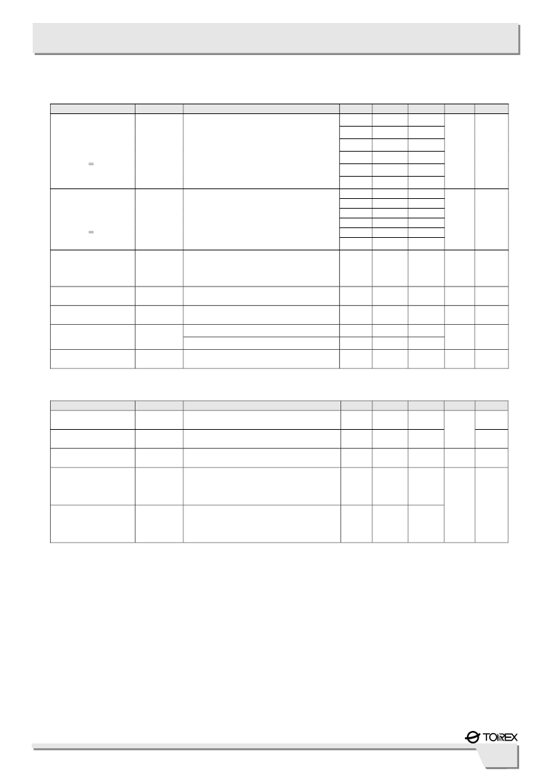
PARAMETER
SYMBOL
CONDITIONS
MIN.
3.13
25
60
120
240
960
3.13
25
60
120
240
960
TYP.
6.25
50
100
200
400
1600
6.25
50
100
200
400
1600
MAX.
9.38
75
140
280
560
2240
9.38
75
140
280
560
2240
UNITS
CIRCUIT
Watchdog
Timeout Period
(V
DF
<1.8V)
T
WD
Time until V
IN
increases form
1.0V to 2.0V and
the Reset output pin is released to go into
the detection state. (WD=V
SS
)
ms
6
Watchdog
Timeout Period
(V
DF
>1.9V)
T
WD
Time until V
IN
increases form
1.0V to (V
DF
x1.1V)
and the Reset output pin is released to go
into the detection state. (WD=V
SS
)
ms
6
Watchdog
Minimum Pulse Width
T
WDIN
V
IN
=6.0V,
Apply pulse from 6.0V to 0V
to the WD pin.
300
-
-
ns
7
Watchdog
High Level Voltage
Watchdog
Low Level Voltage
Watchdog
Input Current
Watchdog
Input Resistance
V
WDH
V
IN
=V
DF
x 1.1V ~ 6.0V
V
IN x
0.7
-
6
V
7
V
WDL
V
IN
=V
DF
x 1.1V ~ 6.0V
0
-
V
IN x
0.3
V
7
V
IN
=6.0V, V
WD
=6.0V (Avg. when peak )
V
IN
=6.0V, V
WD
=0V (Avg. when peak)
-
12
-12
19
I
WD
- 19
-
μ
A
8
R
WD
V
IN
=6.0V, V
WD
=0V, R
WD
=V
IN
/ |I
WD
|
315
500
880
k
8
PARAMETER
MRB
High Level Voltage
MRB
Low Level Voltage
MRB
Pull-up Resistance
MRB Minimum
Pulse Width (*3)
XC6101~XC6105
XC6111~XC6115
MRB Minimum
Pulse Width (*4)
XC6106, XC6107
XC6116, XC6117
SYMBOL
CONDITIONS
MIN.
TYP.
MAX.
UNITS
CIRCUIT
V
MRH
V
IN
=V
DF
x1.1V ~ 6.0V
1.4
-
V
IN
9
V
MRL
V
IN
=V
DF
x1.1V ~ 6.0V
0
-
0.35
V
9
R
MR
V
IN
=6.0V, MRB=0V, R
MR
=V
IN
/ |I
MRB
|
1.6
2.4
3.0
M
10
T
MRIN
V
IN
=6.0V,
Apply pulse from 6.0V to 0V to
the MRB pin
2.8
-
-
T
MRIN
V
IN
=6.0V,
Apply pulse from 6.0V to 0V to
the MRB pin
1.2
-
-
μ
s
11
●
XC6101 ~ XC6103, XC6106 ~ XC6107, XC6111 ~ XC6113, XC6116 ~ XC6117 Series
NOTE:
*1: V
DF(T)
: Setting detect voltage
*2: If only “V
DF
” is indicated, it represents both V
DFL
(low when detected) and V
DFH
(high when detected).
*3: Watchdog function is available.
*4: Watchdog function is not available.
Ta = 25
O
C
Ta = 25
O
C
■
ELECTRICAL CHARACTERISTICS (Continued)
●
XC6101~XC6105, XC6111~XC6115 Series
相關(guān)PDF資料 |
PDF描述 |
|---|---|
| XC6114E626 | CMOS Voltage Detector |
| XC6114E627 | CMOS Voltage Detector |
| XC6114E628 | CMOS Voltage Detector |
| XC6114E629 | CMOS Voltage Detector |
| XC6114E630 | CMOS Voltage Detector |
相關(guān)代理商/技術(shù)參數(shù) |
參數(shù)描述 |
|---|---|
| XC6115B230MR-G | 制造商:Torex Semiconductor LTD 功能描述: |
| XC6115B330MRN | 制造商:Torex Semiconductor LTD 功能描述: |
| XC6118N09AMR-G | 制造商:Torex Semiconductor LTD 功能描述: |
| XC6118N10AMR-G | 制造商:Torex Semiconductor LTD 功能描述: |
| XC6118N13AMR-G | 制造商:Torex Semiconductor LTD 功能描述: |
發(fā)布緊急采購,3分鐘左右您將得到回復(fù)。