- 您現(xiàn)在的位置:買賣IC網(wǎng) > PDF目錄372584 > XC6111A234 (TOREX SEMICONDUCTOR LTD.) CMOS Voltage Detector PDF資料下載
參數(shù)資料
| 型號(hào): | XC6111A234 |
| 廠商: | TOREX SEMICONDUCTOR LTD. |
| 英文描述: | CMOS Voltage Detector |
| 中文描述: | CMOS電壓檢測(cè)器 |
| 文件頁數(shù): | 2/26頁 |
| 文件大小: | 535K |
| 代理商: | XC6111A234 |
第1頁當(dāng)前第2頁第3頁第4頁第5頁第6頁第7頁第8頁第9頁第10頁第11頁第12頁第13頁第14頁第15頁第16頁第17頁第18頁第19頁第20頁第21頁第22頁第23頁第24頁第25頁第26頁

XC6101~XC6107, XC6111~XC6117 Series
2/26
PIN NUMBER
XC6103
XC6113
XC6101, XC6102
XC6111, XC6112
SOT-25 USP-6C SOT-25 USP-6C SOT-25 USP-6C SOT-25 USP-6C
XC6104, XC6105 XC6106, XC6107
XC6114, XC6115 XC6116, XC6117
PIN NAME
FUNCTION
1
4
-
-
1
4
1
4
R
ESETB
Reset Output
(V
DFL
: Low Level When Detected)
Ground
2
5
2
5
2
5
2
5
V
SS
3
2
3
2
-
-
4
1
M
RB
Manual Reset
4
1
4
1
4
1
-
-
WD
Watchdog
5
6
5
6
5
6
5
6
V
IN
Power Input
-
-
1
4
3
2
3
2
RESET
Reset Output
(V
DFH:
High Level When Detected)
■
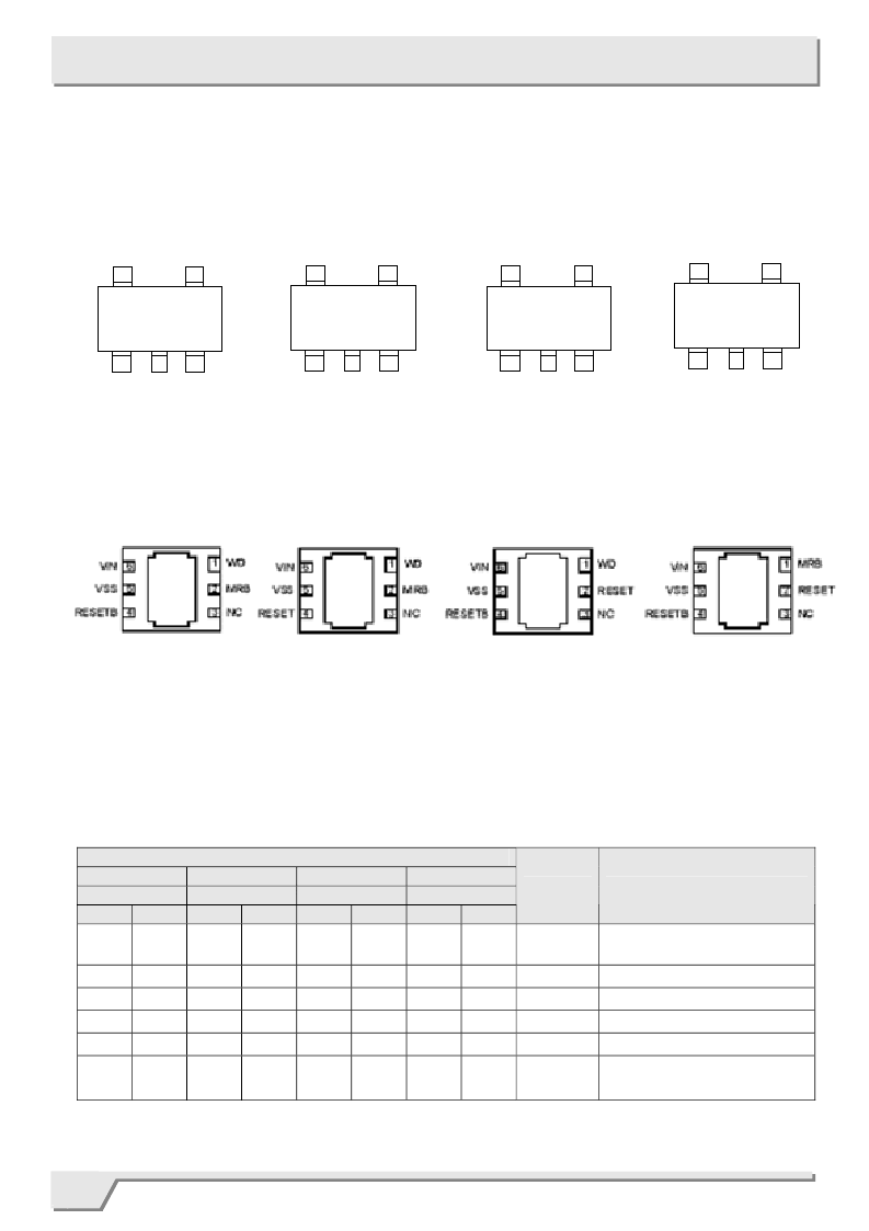
PIN CONFIGURATION
SOT-25 (TOP VIEW)
MRB
V
IN
WD
5
RESETB
V
SS
4
1
2
3
MRB
WD
5
RESET
V
SS
4
1
2
3
V
IN
RESET
WD
5
RESETB
V
SS
4
1
2
3
V
IN
SOT-25 (TOP VIEW)
RESET
MRB
5
RESETB
V
SS
4
1
2
3
V
IN
SOT-25 (TOP VIEW)
■
PIN ASSIGNMENT
●
SOT-25
XC6101, XC6102 Series
XC6111, XC6112 Series
SOT-25 (TOP VIEW)
XC6103 & XC6113 Series
XC6104, XC6105 Series
XC6114, XC6115 Series
XC6106, XC6107 Series
XC6116, XC6117 Series
●
USP-6C
XC6101, XC6102 Series
XC6111, XC6112 Series
XC6103 & XC6113 Series
XC6104, XC6105 Series
XC6114, XC6115 Series
XC6106, XC6107 Series
XC6116, XC6117 Series
USP-6C (BOTTOM VIEW)
USP-6C (BOTTOM VIEW)
USP-6C (BOTTOM VIEW)
USP-6C (BOTTOM VIEW)
* The dissipation pad for the USP-6C package should be
solder-plated in recommended mount pattern and metal
masking so as to enhance mounting strength and heat
release. If the pad needs to be connected to other pins, it
should be connected to the V
SS
pin.
相關(guān)PDF資料 |
PDF描述 |
|---|---|
| XC6111A235 | CMOS Voltage Detector |
| XC6111A236 | CMOS Voltage Detector |
| XC6111A237 | CMOS Voltage Detector |
| XC6111A238 | CMOS Voltage Detector |
| XC6111A239 | CMOS Voltage Detector |
相關(guān)代理商/技術(shù)參數(shù) |
參數(shù)描述 |
|---|---|
| XC6115B230MR-G | 制造商:Torex Semiconductor LTD 功能描述: |
| XC6115B330MRN | 制造商:Torex Semiconductor LTD 功能描述: |
| XC6118N09AMR-G | 制造商:Torex Semiconductor LTD 功能描述: |
| XC6118N10AMR-G | 制造商:Torex Semiconductor LTD 功能描述: |
| XC6118N13AMR-G | 制造商:Torex Semiconductor LTD 功能描述: |
發(fā)布緊急采購,3分鐘左右您將得到回復(fù)。