- 您現(xiàn)在的位置:買賣IC網(wǎng) > PDF目錄371287 > X9312SP Interface IC PDF資料下載
參數(shù)資料
| 型號: | X9312SP |
| 英文描述: | Interface IC |
| 中文描述: | 接口IC |
| 文件頁數(shù): | 2/9頁 |
| 文件大小: | 50K |
| 代理商: | X9312SP |

X9312
2
PIN DESCRIPTIONS
V
H
and V
L
The high (V
H
) and low (V
L
) terminals of the X9312
are equivalent to the fixed terminals of a mechanical
potentiometer. The minimum voltage is 0V and the
maximum is +15V. It should be noted that the
terminology of V
L
and V
H
references the relative position
of the terminal in relation to wiper movement direction
selected by the U/
D
input and not the voltage potential on
the terminal.
V
W
Vw is the wiper terminal, equivalent to the movable
terminal of a mechanical potentiometer. The position
of the wiper within the array is determined by the
control inputs. The wiper terminal series resistance is
typically 40
.
Up/Down (U/
D
)
The U/
D
input controls the direction of the wiper move-
ment and whether the counter is incremented or
decremented.
Increment (
INC
)
The
INC
input is negative-edge triggered. Toggling
INC
will move the wiper and either increment or decrement
the counter in the direction indicated by the logic level on
the U/
D
input.
Chip Select (
CS
)
The device is selected when the
CS
input is LOW. The
current counter value is stored in nonvolatile memory
when
CS
is returned HIGH while the
INC
input is also
HIGH. After the store operation is complete the X9312
will be placed in the low power standby mode until the
device is selected once again.
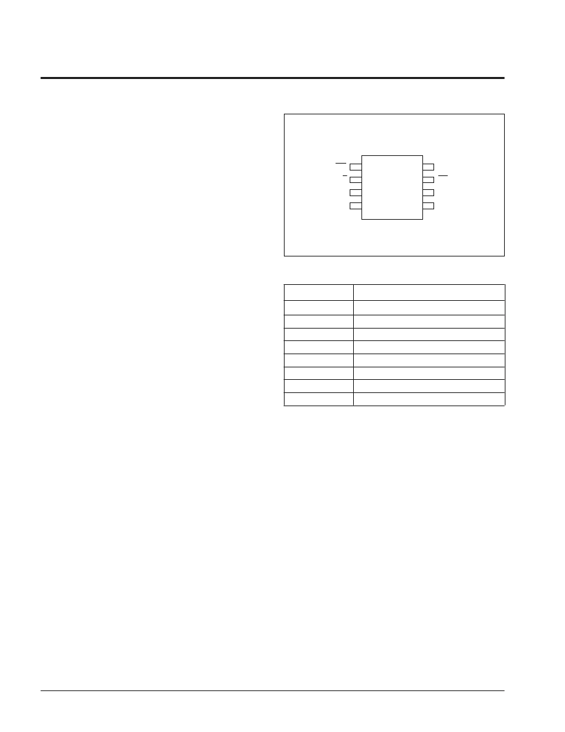
PIN CONFIGURATION
PIN NAMES
Symbol
Description
V
H
V
W
V
L
V
SS
V
CC
U/
D
INC
CS
High Terminal
Wiper Terminal
Low Terminal
Ground
Supply Voltage
Up/Down Input
Increment Input
Chip Select Input
3865 PGM T01
VCC
CS
VL
VW
3863 FHD F02.1
INC
U/D
VH
VSS
1
2
3
4
8
7
6
5
X9312
DIP/SOIC
相關PDF資料 |
PDF描述 |
|---|---|
| X9312SPI | RF inductor, ceramic core, 2% tol, SMT, RoHS |
| X9312SPM | Interface IC |
| X9312WP | E2POT⑩ Nonvolatile Digital Potentiometer |
| X9312WPI | E2POT⑩ Nonvolatile Digital Potentiometer |
| X9312WPM | E2POT⑩ Nonvolatile Digital Potentiometer |
相關代理商/技術參數(shù) |
參數(shù)描述 |
|---|---|
| X9312SPI | 制造商:未知廠家 制造商全稱:未知廠家 功能描述:Interface IC |
| X9312SPM | 制造商:未知廠家 制造商全稱:未知廠家 功能描述:Interface IC |
| X9312TP | 制造商:XICOR 制造商全稱:Xicor Inc. 功能描述:E2POT⑩ Nonvolatile Digital Potentiometer |
| X9312TPI | 制造商:XICOR 制造商全稱:Xicor Inc. 功能描述:E2POT⑩ Nonvolatile Digital Potentiometer |
| X9312TPM | 制造商:XICOR 制造商全稱:Xicor Inc. 功能描述:E2POT⑩ Nonvolatile Digital Potentiometer |
發(fā)布緊急采購,3分鐘左右您將得到回復。