- 您現(xiàn)在的位置:買賣IC網(wǎng) > PDF目錄225520 > VF961SHL-FREQ (VALPEY FISHER CORP) VCXO, CLOCK, 10 MHz - 200 MHz, LVPECL OUTPUT PDF資料下載
參數(shù)資料
| 型號(hào): | VF961SHL-FREQ |
| 廠商: | VALPEY FISHER CORP |
| 元件分類: | VCXO, clock |
| 英文描述: | VCXO, CLOCK, 10 MHz - 200 MHz, LVPECL OUTPUT |
| 文件頁數(shù): | 1/1頁 |
| 文件大小: | 25K |
| 代理商: | VF961SHL-FREQ |
VCXO
VF960/961
75 South Street, Hopkinton, MA 01748
800-982-5737
508-435-6831
Fax: 508-435-5289 www.valpeyfisher.com
80
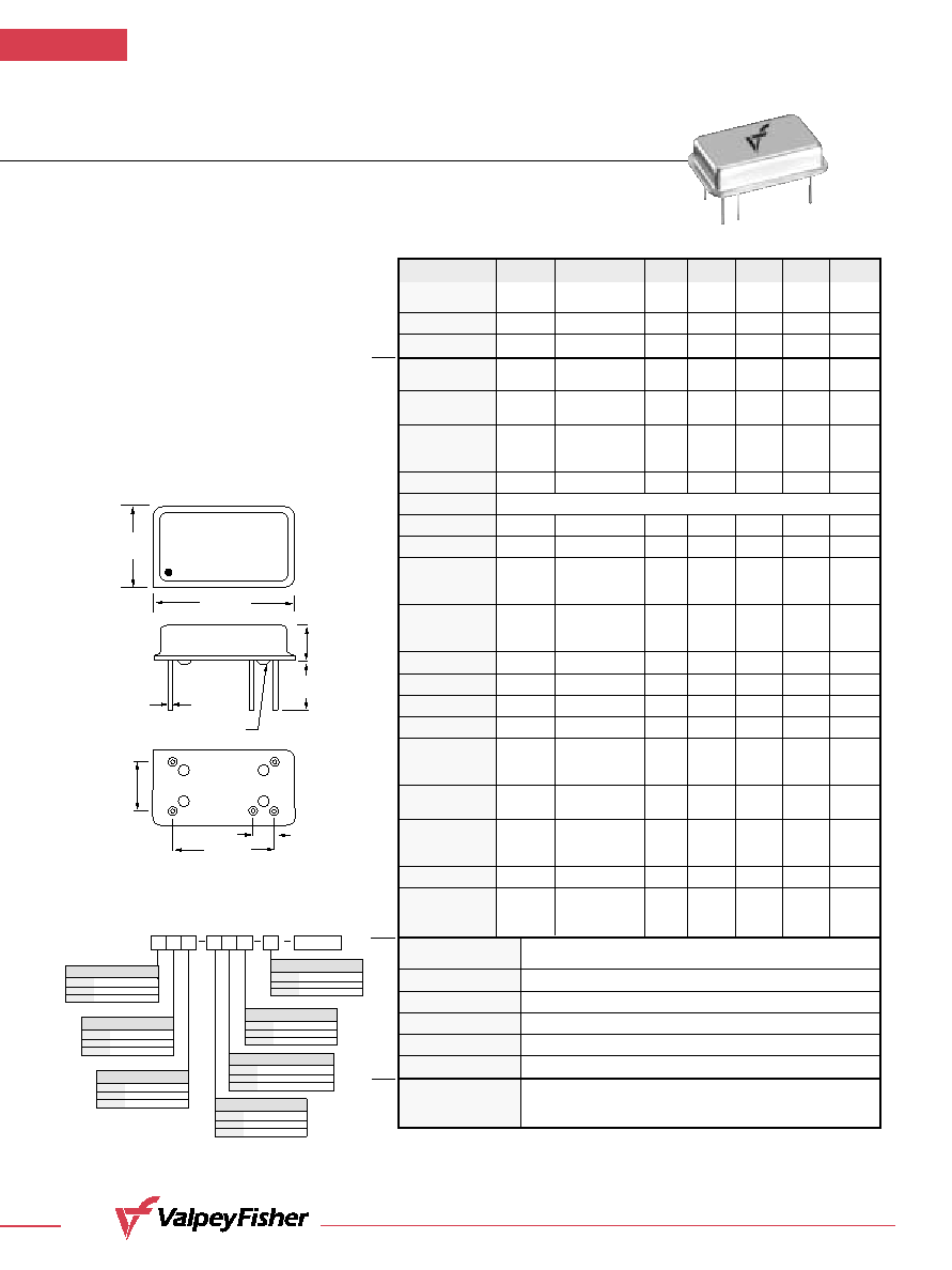
VF960/VF961
ECL/PECL Compatible Hybrid VCXO
Standard 14 Pin DIP Package
FEATURES
No Frequency Multiplication is Used
Very Low Phase Jitter
Low Component Count
Pullability (±500 ppm available)
Temperature Range
(–40°C to +85°C) Available
Complementary Output Available
Wide Frequency Range
0.300"
(7,62mm)
0.600"
(15,24mm)
.187"
(4,75mm)
0.100"
(2,54mm)
GLASS STANDOFFS
0.0180"
(0,460mm)
0.800"
(20,32mm)
0.497"
(12,62mm)
VALPEYFISHER
VF961
155.52MHZ
BO1H
#1
#7
#8
#14
#9
*
0.250"
(6,35mm)
Creating a Part Number
VF960/961
LEAD CONFIGURATION
Code
Specification
G
Gull Wing
Through Hole (std.)
INPUT VOLTAGE
Code
Specification
L
3.3 Volt
±5%*
5.0 Volt
±5% (std.)
OPERATIONAL TEMP. RANGE
Code
Specification
0
°C to +70°C (std.)
1
-40
°C to +85°C
FREQUENCY STABILITY
Code
Specification
S
±20
ppm
±25
ppm (std.)
ABSOLUTE PULL RANGE (ppm)
Code
Specification
±50 ppm MIN. (std.)
XXX
up to 500 ppm
(customer specified)
OUTPUT
Code
Specification
C
Complementary
4 pin pkg Single (std.)
(*VF961 Only)
DUTY CYCLE
Code
Specification
H
±5%
±10% (std.)
Example: VF960SHL-1CG-100-106.25MHz: Frequency Stability
±20ppm,
Duty Cycle
±5%, Input Voltage 3.3 Volt ±5%, Operating Temperature
-40
°C to +85°C, Complementary Output (5-pin package), Gull Wing,
APR
±100ppm, Frequency 106.25MHz.
FREQ.
Parameter
Symb
Condition
Min
Typ
Max
Unit
Note
Input Break
Vcc–Vee
–.5
7.0
V
Down Voltage
Storage Temp.
Ts
–40
+85
°C
Control Voltage
Vc
–1.0
9.0
V
Frequency
Range
F
10
200
MHz
Frequency
F/F
Over Temp, Vcc
±25
ppm
Stability
Input Voltage
Vcc
PECL
4.75
5.00
5.25
VF961
Vee
ECL
–4.95
–5.20
–5.45
VF960
Vcc
LVPECL
3.15
3.30
3.45
VF961L
Input Current
Icc/Iee
50 Ohm Load
65
mA
Load
Duty Cycle
@50%
40
50
60
%
1
Rise/Fall Time
Tr/Tf
20% to 80%
1.5
ns
Logic “1” Level
Voh
@Vcc = 5.0V
4.04
4.19
V
PECL
@Vee = –5.2V
–0.96
–0.81
ECL
@Vcc = 3.3V
2.59
2.74
LVPECL
Logic “0” Level
Vol
@Vcc = 5.0V
3.15
3.25
V
PECL
@Vee = –5.2V
–1.85
–1.65
ECL
@Vcc = 3.3V
1.45
1.55
LVPECL
Start–up Time
Ts
2
10
ms
Phase Jitter
1
σ
1
ps
fj>1KHz
Modulation BW
fm
@ Vc = 2.5V
10
KHz
@–3db
Input Impedance
fm<10KHz
50
KOhm
Control Voltage
Vc
PECL
0.0
5.0
V
2
ECL
–5.0
0.0
LVPECL
0.0
3.3
Absolute
APR
Overall
±50
ppm
3
Pull Range
Deviation Slope
Monotonic, pos.
50
ppm/V
PECL
Monotonic, neg.
–50
ECL
Monotonic, pos.
75
LVPECL
Linearity
±20
%
4
Setability (Vc
Vc0
@25°C, Fnominal 2.00
2.50
3.00
V
PECL
for center freq)
–2.00
–2.50
–3.00
ECL
1.25
1.65
2.05
LVPECL
Operating
Temperature Range
0°C to +70°C (–40°C to +85°C available)
Mechanical Shock
Per MIL–STD–202, Method 213, Cond. E
Thermal Shock
Per MIL–STD–883, Method 1011, Cond. A
Vibration
Per MIL–STD–883, Method 2007, Cond. A
Soldering Conditions
260°C, for 10s, Max.
Hermetic Seal
Leak rate less than 5 x 10⁻⁸ atm.cc/s of helium
Pin Out
Pin #1–Voltage Control
Pin #7–Ground, Case (PECL)/–Vee(ECL)
Pin #8–Output
Pin #14–Vcc (PECL)/Case,Ground (ECL)
Pin #9–Complementary Output (Optional)
50 Ohm to Vcc–2V or Thevenin Equiv. Bias required
Absolute
Max.
Ratings
Electrical
Environmental and
Mechanical
Electrical
Connections Notes:
1. Tighter duty cycle available.
2. 0V to 5V control voltage available for Vcc 3.3V. Nominal control voltage is 2.5V
and setability is ±0.5V in this case.
3. Wider pullability available.
4. 10% and 5% available.
All dimensions are typical unless otherwise specified.
* Pin 9 optional
相關(guān)PDF資料 |
PDF描述 |
|---|---|
| VF961SHL1-FREQ | VCXO, CLOCK, 10 MHz - 200 MHz, LVPECL OUTPUT |
| VF961SHLCG-FREQ | VCXO, CLOCK, 10 MHz - 200 MHz, LVPECL OUTPUT |
| VFAC570SHHL-53.125MHZ | CRYSTAL OSCILLATOR, CLOCK, 53.125 MHz, HCMOS/TTL OUTPUT |
| VFAC570AH-2-FREQ | CRYSTAL OSCILLATOR, CLOCK, 4 MHz - 160 MHz, HCMOS/TTL OUTPUT |
| VFC-P-1000 | VCO, 1000 MHz - 2000 MHz |
相關(guān)代理商/技術(shù)參數(shù) |
參數(shù)描述 |
|---|---|
| VF-9HU | 功能描述:通用繼電器 POWER RoHS:否 制造商:Omron Electronics 觸點(diǎn)形式:1 Form A (SPST-NO) 觸點(diǎn)電流額定值:150 A 線圈電壓:24 VDC 線圈電阻:144 Ohms 線圈電流:167 mA 切換電壓:400 V 安裝風(fēng)格:Chassis 觸點(diǎn)材料: |
| VF-9LU | 制造商:FUJITSU Component Ltd 功能描述: |
| VF-9MU | 功能描述:通用繼電器 POWER RoHS:否 制造商:Omron Electronics 觸點(diǎn)形式:1 Form A (SPST-NO) 觸點(diǎn)電流額定值:150 A 線圈電壓:24 VDC 線圈電阻:144 Ohms 線圈電流:167 mA 切換電壓:400 V 安裝風(fēng)格:Chassis 觸點(diǎn)材料: |
| VFA0039 | 制造商:Panasonic Industrial Company 功能描述:CABLE |
| VFA0297 | 制造商:Panasonic Industrial Company 功能描述:ADAPTOR |
發(fā)布緊急采購,3分鐘左右您將得到回復(fù)。