- 您現(xiàn)在的位置:買賣IC網(wǎng) > PDF目錄225527 > VAPL (POSITRONIC INDUSTRIES INC) FEMALE; MALE, TELECOM AND DATACOM CONNECTOR, SOLDER PDF資料下載
參數(shù)資料
| 型號(hào): | VAPL |
| 廠商: | POSITRONIC INDUSTRIES INC |
| 元件分類: | 電信和以太網(wǎng)連接器 |
| 英文描述: | FEMALE; MALE, TELECOM AND DATACOM CONNECTOR, SOLDER |
| 文件頁數(shù): | 1/6頁 |
| 文件大小: | 136K |
| 代理商: | VAPL |

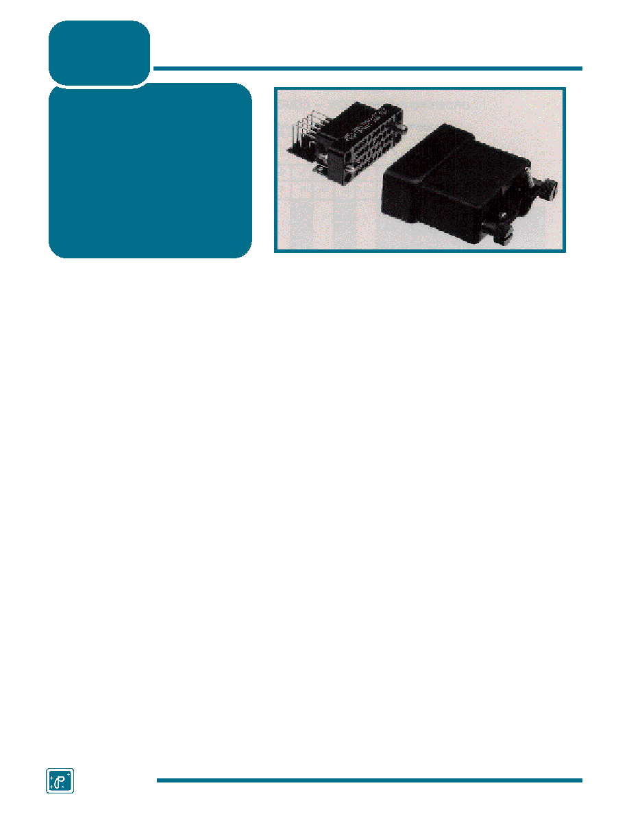
VMCT and VAPL series connectors are high reliability con-
nectors meeting international standards for CCITT V.35 inter-
facing. To meet these specifications, VMCT and VAPL series
connectors come in 34 position glass filled DAP insulators with
0.062 inch (1.57mm) diameters, size 16 contacts rated to 13
amperes.
VMCT Series connectors are offered in crimp, solder cup,
printed board mount, press-fit and wrap post terminations.
VAPL Series connectors have right angle printed board mount
terminations. VMCT and VAPL series connectors meet perfor-
mance requirements for MIL-DTL-28748 and MIL-C-39029.
A wide array of mounting, locking, shrouding and polarizing
accessories is available for these connectors. For details, see
the Heavy-Duty Rectangular Connector Accessories section,
GMCT 34 variant.
VMCT and VAPL series connectors were specifically
designed to satisfy requirements for V.35 interfacing and high
speed data transmission found in the telecommunications,
modem and computer industries. These connectors fully com-
ply with the contact and jackscrew system requirements of ISO
standard 2593, as revised by ISO TC 97/SC6 N 2599 and
3236.
MILITARY SPECIFICATIONS:
Qualified to MIL-DTL-28748/3 and MIL-
DTL-28748/4.
Contacts qualified to
MIL-C-39029/34 and MIL-C-39029/35.
INTERNATIONAL STANDARDS:
IEC 807-1 and IEC 807-7.
U.L. Recognized.
MATERIALS AND FINISHES:
Insulator:
Glass filled DAP per ASTM-D-5948 type
SDG-F.
Grey color is standard, black
available.
Removable Contacts:
Copper alloy with gold flash over nickel.
Military contacts plated 0.000050 inch (1.27
microns) gold over copper. Other finishes
available upon request.
Hoods, Cable Adapters:
Aluminum with yellow or black anodize.
Steel with zinc plate and dichromate
seal.
Shells:
Aluminum with yellow or black anodize.
Jackscrew System:
Passivated stainless steel.
Polarizing Guides:
Copper alloy with nickel plate or passi-
vated stainless steel.
Vibration Locks:
Copper alloy with zinc plate and dichro-
mate seal.
MECHANICAL CHARACTERISTICS:
Removable Contacts:
Insert contact to rear face of insulator,
release from front face of insulator. Size
16
(13 amps.)
contacts available.
Female contact has “closed entry”
design for highest reliability.
Contact Retention in Insulator: 20 lbs. (89N) after 10 cycles of contact
insertion extraction.
Contact Termination:
Crimp all wire sizes from 14 AWG (2.5
mm2) through 32 AWG (0.03 mm2).
Solder cup, wrap post, press-fit and
printed board mount.
Locking Systems:
Friction, vibration locks and jackscrews.
Polarization:
Polarized guides, polarized shells and
jackscrew system.
Mechanical Operations:
1000 operations per IEC 512-5.
Jackscrews:
Standard threads, 6-32 UNC. Metric
threads, M3X0.5 available.
ELECTRICAL CHARACTERISTICS:
Contact Current Rating:
Size 16: 0.062 inch(1.57 mm) diameter
– 13 amps nominal.
Initial ContactResistance:
Size 16 – 0.003 ohms.
Flash over Voltage:
2700 V.AC (rms).
Test Voltage:
Size 16 – 2000 V.AC (rms).
Insulation Resistance
(minimum):
5 G ohms.
Clearance and Creepage
Distance (minimum):
0.080 inch (2.03 mm).
Working Temperature:
-55°C to 125°C.
Working Voltage:
250 V.AC (rms).
V.35 SERIES TECHNICAL CHARACTERISTICS
Size 16 Contacts
Connectors Qualified to
MIL-DTL-28748
Contacts Qualified to
MIL-C-39029
IEC Publication 807-7
ISO International
Standard 2593
U.L. Recognized, File #E49351
Telecommunication U.L. File #E140980
HEAVY-DUTY RECTANGULAR CCITT V.35
INTERFACE CONNECTORS
V.35
Series
P o s i t ro n i c
I n d u s t r i e s
47
VMCT SERIES CONNECTORS WITH REMOVABLE CONTACTS
相關(guān)PDF資料 |
PDF描述 |
|---|---|
| VME-64SD1-16MSF5-03 | Converter |
| VME-64SD1-16MSF6-04 | Converter |
| VME-64SD1-16MSF6-05 | Converter |
| VME-64SD1-16MSF6-06 | Converter |
| VME-64SD1-16MSF6-07 | Converter |
相關(guān)代理商/技術(shù)參數(shù) |
參數(shù)描述 |
|---|---|
| VA-PSU-EU1 | 制造商:Future Technology Devices International (FTDI Chip) 功能描述:POWER SUPPLY 5V 1A USB EU PLUG 制造商:Future Technology Devices International (FTDI Chip) 功能描述:PSU, USB EU MODEL, 5V/1A, Accessory Type:EU Model USB Power Supply, For Use With |
| VA-PSU-UK1 | 制造商:FTDI 制造商全稱:FTDI 功能描述:Embedded Video Engine Credit Card Board |
| VA-PSU-US1 | 制造商:FTDI 制造商全稱:FTDI 功能描述:Embedded Video Engine Credit Card Board |
| VAQ-0V-15-1C5 | 制造商:Omron Electronic Components LLC 功能描述:SWITCH PUSHBUTTON SPDT 制造商:Omron Electronic Components LLC 功能描述:SWITCH, PUSHBUTTON, SPDT |
| VAQ-0V-15-1C5 | 制造商:Omron Electronic Components LLC 功能描述:SWITCH PUSHBUTTON SPDT |
發(fā)布緊急采購,3分鐘左右您將得到回復(fù)。