- 您現(xiàn)在的位置:買賣IC網(wǎng) > PDF目錄361658 > V375A2V5C200A2 DC to DC Converter PDF資料下載
參數(shù)資料
| 型號: | V375A2V5C200A2 |
| 英文描述: | DC to DC Converter |
| 中文描述: | DC至DC轉(zhuǎn)換器 |
| 文件頁數(shù): | 5/8頁 |
| 文件大小: | 185K |
| 代理商: | V375A2V5C200A2 |

Vicor Corp.
Tel: 800-735-6200, 978-470-2900 Fax: 978-475-6715
375V Maxi Family
Rev. 6.1
Page 5 of 8
Set your site on VICOR at www.vicorpower.com
Output Voltage Programming
The output voltage of the converter can be adjusted or
programmed via fixed resistors, potentiometers or voltage
DACs. See Figures 7 and 8.
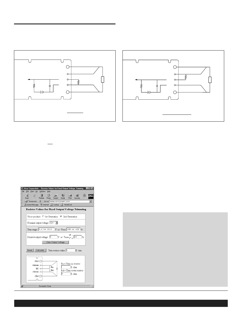
CONTROLFUNCTIONS - SC PIN
Figure 8
—Output voltage trim up circuit.
Figure 7
—Output voltage trim down circuit.
R
D
(ohms) = 1,000 Vout
Vnom - Vout
+Out
+S
SC
–
S
–
Out
R
Trim Up
Load
Error
Amp
1k
1.23V
0.033
μ
F
Load
+Out
+S
SC
–
S
–
Out
R
Trim Down
Error
Amp
1k
1.23V
0.033
μ
F
Trim Down
1. This converter is not a constant power device – it has a
constant current limit. Hence, available output power is
reduced by the same percentage that output voltage is
trimmed down. Do not exceed maximum rated output current.
2. The trim down resistor must be connected to the –Sense pin.
Trim Up
1. The converter is rated for a maximum delivered power. To ensure
that maximum rated power is not exceeded, reduce maximum
output current by the same percentage increase in output voltage.
2. The trim up resistor must be connected to the +Sense pin.
3. Do not trim the converter above maximum trim range
(typically +10%) or the output over voltage
protection circuitry may be activated.
R
U
(ohms) = 1,000
(
Vout-1.23
)
Vnom
1.23
(
Vout-Vnom
)
–
1,000
Trim resistor values calculated automatically:
On-line calculators for trim resistor values are available
on the vicor website at: vicorpower.com/tools.html.
Resistor values can be calculated for fixed trim up, fixed
trim down and for variable trim up or down cases for both
1st and 2nd Generation DC-DC converters.
In addition to trimming information, the web site and the
Applications Manual also include design tips, applications
circuits, EMC suggestions, thermal design guidelines and
PDF data sheets for all available Vicor products.
相關(guān)PDF資料 |
PDF描述 |
|---|---|
| V375A2V5C200A3 | DC to DC Converter |
| V375A2V5C200AL | DC to DC Converter |
| V375A2V5C200AL2 | DC to DC Converter |
| V375A2V5C200AL3 | DC to DC Converter |
| V375A3V3C264A | DC to DC Converter |
相關(guān)代理商/技術(shù)參數(shù) |
參數(shù)描述 |
|---|---|
| V375A2V5C200A3 | 制造商:未知廠家 制造商全稱:未知廠家 功能描述:DC to DC Converter |
| V375A2V5C200AL | 制造商:未知廠家 制造商全稱:未知廠家 功能描述:DC to DC Converter |
| V375A2V5C200AL2 | 制造商:未知廠家 制造商全稱:未知廠家 功能描述:DC to DC Converter |
| V375A2V5C200AL3 | 制造商:未知廠家 制造商全稱:未知廠家 功能描述:DC to DC Converter |
| V375A3.3C150A | 制造商:未知廠家 制造商全稱:未知廠家 功能描述:Analog IC |
發(fā)布緊急采購,3分鐘左右您將得到回復(fù)。