- 您現(xiàn)在的位置:買賣IC網(wǎng) > PDF目錄359311 > V111HB34 (Littelfuse, Inc.) Varistor Products - High Energy Industrial PDF資料下載
參數(shù)資料
| 型號: | V111HB34 |
| 廠商: | Littelfuse, Inc. |
| 元件分類: | 壓敏電阻 |
| 英文描述: | Varistor Products - High Energy Industrial |
| 中文描述: | 壓敏電阻器產(chǎn)品-高能源產(chǎn)業(yè) |
| 文件頁數(shù): | 2/8頁 |
| 文件大?。?/td> | 211K |
| 代理商: | V111HB34 |
102
www.littelfuse.com
Varistor Products
High Energy Industrial
HB34, HF34 and HG34 Varistor Series
Absolute Maximum Ratings
For ratings of individual members of a series, see Device Ratings and Specifications chart
Continuous:
Steady State Applied Voltage:
AC Voltage Range (VM(AC)RMS) . . . . . . . . . . . . . . . . . . . . . . . . . . . . . . . . . . . . . . . . . . . . . . . . . . . . . . . . . . . . . . . . . . . . . 110 to 750
DC Voltage Range (VM(DC)) . . . . . . . . . . . . . . . . . . . . . . . . . . . . . . . . . . . . . . . . . . . . . . . . . . . . . . . . . . . . . . . . . . . . . . . . . 148 to 970
Transient:
Peak Pulse Current (ITM)
For 8/20μs Current Wave (See Figure 2) . . . . . . . . . . . . . . . . . . . . . . . . . . . . . . . . . . . . . . . . . . . . . . . . . . . . . . . . . . . . . . . . . 40,000
Single Pulse Energy Range
For 2ms Current Square Wave (WTM) . . . . . . . . . . . . . . . . . . . . . . . . . . . . . . . . . . . . . . . . . . . . . . . . . . . . . . . . . . . . . . . . . 220 to 1050
Operating Ambient Temperature Range (TA). . . . . . . . . . . . . . . . . . . . . . . . . . . . . . . . . . . . . . . . . . . . . . . . . . . . . . . . . . . . . . . . -55 to 85
Storage Temperature Range (TSTG). . . . . . . . . . . . . . . . . . . . . . . . . . . . . . . . . . . . . . . . . . . . . . . . . . . . . . . . . . . . . . . . . . . . . . -55 to 125
Temperature Coefficient (
α
V) of Clamping Voltage (VC) at Specified Test Current . . . . . . . . . . . . . . . . . . . . . . . . . . . . . . . . . . . . <0.01
V
V
A
J
O
C
O
C
%/
O
C
CAUTION: Stresses above those listed in “Absolute Maximum Ratings” may cause permanent damage to the device.This is a stress only rating and operation of the device
at these or any other conditions above those indicated in the operational sections of this specification is not implied.
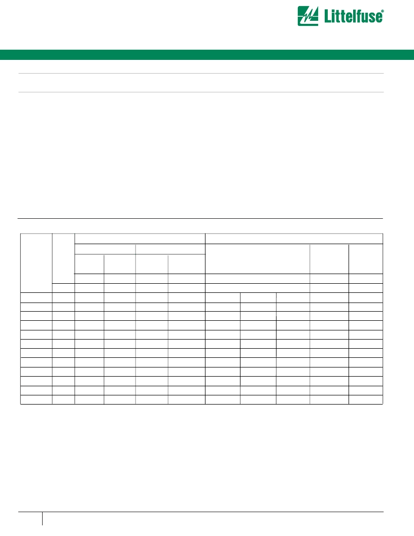
Device Ratings and Specifications
Hx34 SERIES UNITS
MODEL
NUMBER
SIZE
MAXIMUM RATINGS (85
o
C)
SPECIFICATIONS (25
o
C)
CONTINUOUS
TRANSIENT
VARISTOR VOLTAGE
AT 1mA DC TEST
CURRENT
MAXIMUM
CLAMPING
VOLTAGE
(V
C
) AT 200A
(8/20
μ
s)
TYPICAL
CAPACI-
TANCE
V
RMS
V
DC
ENERGY
(2ms)
PEAK
CURRENT
(8/20
μ
s)
V
M(AC)
V
M(DC)
W
TM
I
TM
MIN
V
N(DC)
MAX
V
C
f = 1MHz
(mm)
(V)
(V)
(V)
(A)
(V)
(V)
(V)
(V)
(pF)
V131HB34
V111HB34
34
34
34
130
110
140
175
148
188
270
220
291
40,000
184
156
198
200
173
220
228
190
248
345
288
375
9,000
10,000
11,600
V151HB34
34
150
200
300
40,000
212
240
268
405
8,000
V251HB34
34
250
330
370
40,000
354
390
429
650
5,000
V201HB34
34
200
265
350
40,000
283
314
345
533
6,350
V271HB34
V301HB34
34
34
275
300
370
410
400
430
40,000
40,000
389
433
430
478
473
526
730
780
4,500
4,100
V321HB34
34
320
420
460
40,000
462
510
561
830
3,800
V331HB34
34
330
435
475
40,000
467
519
570
843
3,750
V351HB34
34
350
460
500
40,000
495
550
604
894
3,600
NOTE: Average power dissipation of transients not to exceed 2.0W.
1. Peak current applies to applications rated up to 115 V . Peak current is 30kA for applications greater than 115V .
2. Peak current applies to applications rated up to 123V . Peak Current is 30kA for applications greater than 123V .
3. Peak current applies to applications rated up to 132V . Peak Current is 30kA for applications greater than 132V .
4. Peak current applies to applications rated up to 97V . Peak Current is 30kA for applications greater than 97V .
5. 40kA capability depends on applications rated up to 97Vrms. 30kA applies if >97 Vrms.
RMS
1
40,000
5
40,000
2
RMS
4
V181HB34
34
180
240
330
40,000
254
282
310
468
6,800
V141HB34
相關(guān)PDF資料 |
PDF描述 |
|---|---|
| V120CH8 | Surface Mount Varistors - Transient Voltage Surge Suppressor |
| V12RA8 | Varistor Products - Low Profile |
| V130LA1 | Varistor Products - Line Voltage Operation, Radial Lead |
| V130LA10A | Line Voltage Operation, Radial Lead |
| V130LA10AP | Varistor Products - Line Voltage Operation, Radial Lead |
相關(guān)代理商/技術(shù)參數(shù) |
參數(shù)描述 |
|---|---|
| V111HF34 | 功能描述:壓敏電阻 HIGH ENERGY RoHS:否 制造商:EPCOS 產(chǎn)品:MLV 電壓額定值 DC:22 V 電壓額定值 AC:17 V 鉗位電壓:50 V 直徑: 峰值浪涌電流:30 A 浪涌能量額定值:75 mJ 電容:74.2 pF 工作溫度范圍:- 55 C to + 125 C 安裝:SMD/SMT 封裝:Reel |
| V111HG34 | 功能描述:壓敏電阻 HIGH ENERGY PCB USE RoHS:否 制造商:EPCOS 產(chǎn)品:MLV 電壓額定值 DC:22 V 電壓額定值 AC:17 V 鉗位電壓:50 V 直徑: 峰值浪涌電流:30 A 浪涌能量額定值:75 mJ 電容:74.2 pF 工作溫度范圍:- 55 C to + 125 C 安裝:SMD/SMT 封裝:Reel |
| V111JH64-6KK00-000 | 制造商:Carling Technologies 功能描述:V-SERIES ROCKER SWITCH - Bulk |
| V1-11K | 制造商:STIG RAVN 功能描述:CONTAINER ROUND W/LID 制造商:STIG RAVN 功能描述:CONTAINER, ROUND, W/LID 制造商:STIG RAVN 功能描述:CONTAINER, ROUND, W/LID; External Height - Metric:17.5mm ;RoHS Compliant: NA |
| V111KHHB-00000-000 | 制造商:Carling Technologies 功能描述:V-SERIES ROCKER SWITCH - Bulk |
發(fā)布緊急采購,3分鐘左右您將得到回復(fù)。