- 您現(xiàn)在的位置:買(mǎi)賣(mài)IC網(wǎng) > PDF目錄300064 > UVQ-18/5.6-D24NB 1-OUTPUT DC-DC REG PWR SUPPLY MODULE PDF資料下載
參數(shù)資料
| 型號(hào): | UVQ-18/5.6-D24NB |
| 元件分類(lèi): | 電源模塊 |
| 英文描述: | 1-OUTPUT DC-DC REG PWR SUPPLY MODULE |
| 封裝: | ROHS COMPLIANT |
| 文件頁(yè)數(shù): | 6/9頁(yè) |
| 文件大小: | 612K |
| 代理商: | UVQ-18/5.6-D24NB |
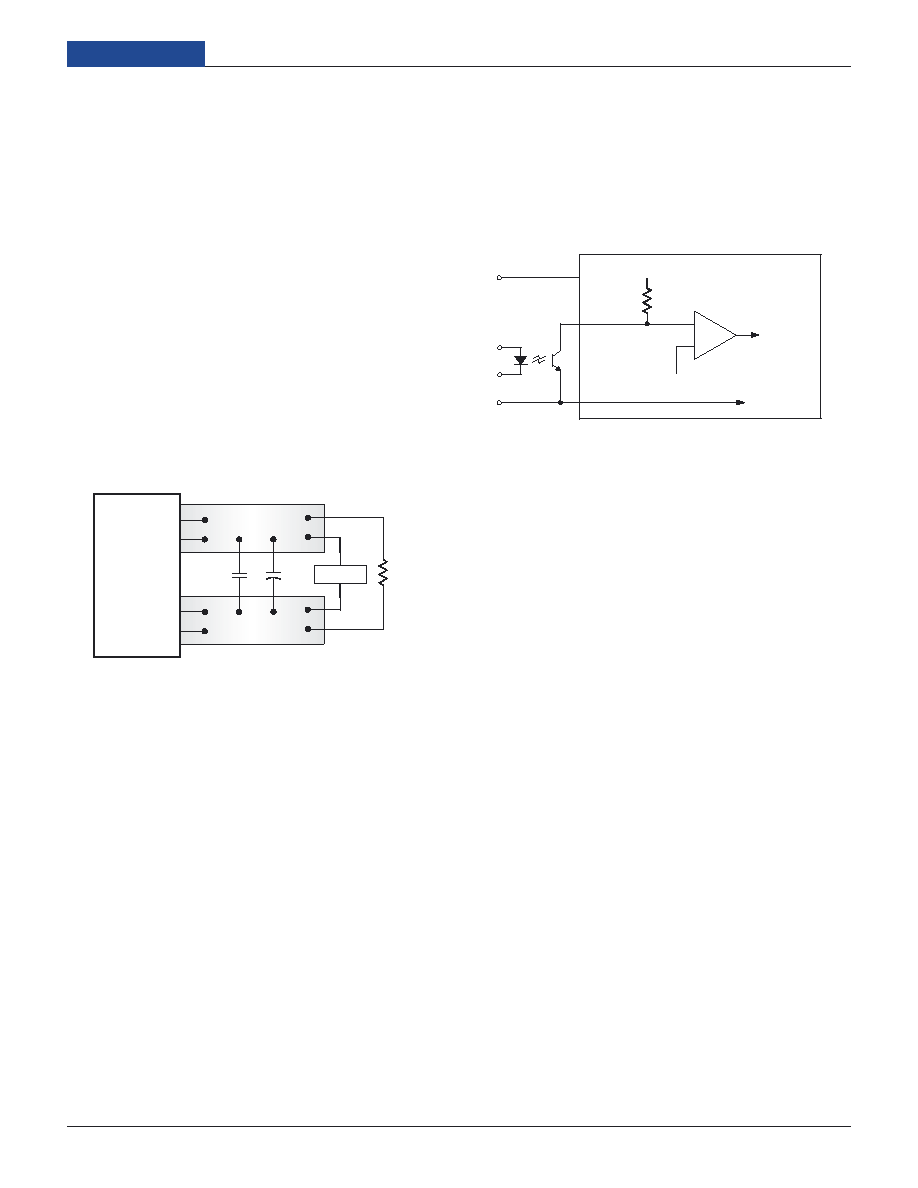
Figure 3. Measuring Output Ripple/Noise (PARD)
Start-Up Threshold and Undervoltage Shutdown
Under normal start-up conditions, the UVQ Series will not begin to regulate
properly until the ramping input voltage exceeds the Start-Up Threshold.
Once operating, devices will turn off when the applied voltage drops below
the Undervoltage Shutdown point. Devices will remain off as long as the
undervoltage condition continues. Units will automatically re-start when the
applied voltage is brought back above the Start-Up Threshold. The hyster-
esis built into this function avoids an indeterminate on/off condition at a single
input voltage. See Performance/Functional Specications table for actual limits.
Start-Up Time
The VIN to VOUT Start-Up Time is the interval between the point at which a
ramping input voltage crosses the Start-Up Threshold voltage and the point
at which the fully loaded output voltage enters and remains within its speci-
ed
±1% accuracy band. Actual measured times will vary with input source
impedance, external input capacitance, and the slew rate and nal value of
the input voltage as it appears to the converter. The On/Off to VOUT start-up
time assumes that the converter is turned off via the Remote On/Off Control
with the nominal input voltage already applied.
C1
C1 = 1F CERAMIC
C2 = 10F TANTALUM
LOAD 2-3 INCHES (51-76mm) FROM MODULE
C2
RLOAD
7
8
COPPER STRIP
4
5
COPPER STRIP
SCOPE
+OUTPUT
–OUTPUT
+SENSE
–SENSE
In critical applications, output ripple/noise (also referred to as periodic and
random deviations or PARD) can be reduced below specied limits using
ltering techniques, the simplest of which is the installation of additional
external output capacitors. Output capacitors function as true lter elements
and should be selected for bulk capacitance, low ESR, and appropriate
frequency response. In Figure 3, the two copper strips simulate real-world
pcb impedances between the power supply and its load. Scope measurements
should be made using BNC connectors or the probe ground should be less
than inch and soldered directly to the xture.
All external capacitors should have appropriate voltage ratings and be
located as close to the converter as possible. Temperature variations for all
relevant parameters should be taken into consideration. OS-CONTM organic
semiconductor capacitors (www.sanyo.com) can be especially effective for
further reduction of ripple/noise.
The most effective combination of external I/O capacitors will be a function
of line voltage and source impedance, as well as particular load and layout
conditions. Our Applications Engineers can recommend potential solutions
and discuss the possibility of our modifying a given device’s internal ltering
to meet your specic requirements. Contact our Applications Engineering
Group for additional details.
On/Off Control
The primary-side, Remote On/Off Control function (pin 2) can be specied to
operate with either positive or negative polarity. Positive-polarity devices ("P"
sufx) are enabled when pin 2 is left open or is pulled high. Positive-polarity
devices are disabled when pin 2 is pulled low (0-0.8V with respect to –Input).
Negative-polarity devices are off when pin 2 is high/open and on when pin 2
is pulled low. See Figure 4.
Dynamic control of the remote on/off function is best accomplished with
a mechanical relay or an open-collector/open-drain drive circuit (optically
isolated if appropriate). The drive circuit should be able to sink appropriate
current (see Performance Specications) when activated and withstand
appropriate voltage when deactivated.
Current Limiting
When power demands from the output falls within the current limit inception
range for the rated output current, the DC/DC converter will go into a current
limiting mode. In this condition the output voltage will decrease proportion-
ately with increases in output current, thereby maintaining a somewhat
constant power dissipation. This is commonly referred to as power limiting.
Current limit inception is dened as the point where the full-power output
voltage falls below the specied tolerance. If the load current being drawn
from the converter is signicant enough, the unit will go into a short circuit
condition. See “Short Circuit Condition.”
Short Circuit Condition
When a converter is in current limit mode the output voltages will drop as
the output current demand increases. If the output voltage drops too low, the
magnetically coupled voltage used to develop primary side voltages will also
drop, thereby shutting down the PWM controller. Following a time-out period
of about 50 milliseconds, the PWM will restart, causing the output voltages to
begin ramping to their appropriate values. If the short-circuit condition per-
sists, another shutdown cycle will be initiated. This on/off cycling is referred
to as “hiccup” mode. The hiccup cycling reduces the average output current,
thereby preventing internal temperatures from rising to excessive levels. The
UVQ is capable of enduring an indenite short circuit output condition.
Thermal Shutdown
UVQ converters are equipped with thermal-shutdown circuitry. If the internal
temperature of the DC/DC converter rises above the designed operating tem-
perature (See Performance Specications), a precision temperature sensor
will power down the unit. When the internal temperature decreases below
the threshold of the temperature sensor, the unit will self start.
Figure 4. Driving the Remote On/Off Control Pin
6
UVQ Series
2 . 5 - 4 0 A M P I S O L A T E D D C / D C C O N V E R T E R S
相關(guān)PDF資料 |
PDF描述 |
|---|---|
| UX40-MB-5PA-1000-2003 | INTERCONNECTION DEVICE |
| UX40-MB-5P | Meet requirements of USB 2.0 |
| UX40-MB-5PA-1000-2003 | Meet requirements of USB 2.0 |
| UX40-MB-5P | INTERCONNECTION DEVICE |
| UX40A-MB-5P | INTERCONNECTION DEVICE |
相關(guān)代理商/技術(shù)參數(shù) |
參數(shù)描述 |
|---|---|
| UVQ-2.5/35-D24N | 制造商:Murata Power Solutions 功能描述:Module DC-DC 1-OUT 2.5V 35A 87.5W 8-Pin Quarter-Brick |
| UVQ-2.5/35-D24NB-C | 功能描述:DC/DC轉(zhuǎn)換器 87.5W 24V - 2.5V 35A NEG POL BASEPLATE RoHS:否 制造商:Murata 產(chǎn)品: 輸出功率: 輸入電壓范圍:3.6 V to 5.5 V 輸入電壓(標(biāo)稱(chēng)): 輸出端數(shù)量:1 輸出電壓(通道 1):3.3 V 輸出電流(通道 1):600 mA 輸出電壓(通道 2): 輸出電流(通道 2): 安裝風(fēng)格:SMD/SMT 封裝 / 箱體尺寸: |
| UVQ-2.5/35-D24N-C | 功能描述:DC/DC轉(zhuǎn)換器 87.5W 24V - 2.5V 35A NEGATIVE POLARITY RoHS:否 制造商:Murata 產(chǎn)品: 輸出功率: 輸入電壓范圍:3.6 V to 5.5 V 輸入電壓(標(biāo)稱(chēng)): 輸出端數(shù)量:1 輸出電壓(通道 1):3.3 V 輸出電流(通道 1):600 mA 輸出電壓(通道 2): 輸出電流(通道 2): 安裝風(fēng)格:SMD/SMT 封裝 / 箱體尺寸: |
| UVQ-2.5/35-D24P | 制造商:Murata Power Solutions 功能描述:Module DC-DC 1-OUT 2.5V 35A 87.5W 8-Pin Quarter-Brick |
| UVQ-2.5/35-D24PB-C | 功能描述:DC/DC轉(zhuǎn)換器 87.5W 24V - 2.5V 35A POS POL BASEPLATE RoHS:否 制造商:Murata 產(chǎn)品: 輸出功率: 輸入電壓范圍:3.6 V to 5.5 V 輸入電壓(標(biāo)稱(chēng)): 輸出端數(shù)量:1 輸出電壓(通道 1):3.3 V 輸出電流(通道 1):600 mA 輸出電壓(通道 2): 輸出電流(通道 2): 安裝風(fēng)格:SMD/SMT 封裝 / 箱體尺寸: |
發(fā)布緊急采購(gòu),3分鐘左右您將得到回復(fù)。