- 您現(xiàn)在的位置:買賣IC網(wǎng) > PDF目錄378742 > UPD6451AGT-101 On-Screen Display Circuit PDF資料下載
參數(shù)資料
| 型號(hào): | UPD6451AGT-101 |
| 英文描述: | On-Screen Display Circuit |
| 中文描述: | 屏幕顯示電路 |
| 文件頁(yè)數(shù): | 24/68頁(yè) |
| 文件大小: | 301K |
| 代理商: | UPD6451AGT-101 |
第1頁(yè)第2頁(yè)第3頁(yè)第4頁(yè)第5頁(yè)第6頁(yè)第7頁(yè)第8頁(yè)第9頁(yè)第10頁(yè)第11頁(yè)第12頁(yè)第13頁(yè)第14頁(yè)第15頁(yè)第16頁(yè)第17頁(yè)第18頁(yè)第19頁(yè)第20頁(yè)第21頁(yè)第22頁(yè)第23頁(yè)當(dāng)前第24頁(yè)第25頁(yè)第26頁(yè)第27頁(yè)第28頁(yè)第29頁(yè)第30頁(yè)第31頁(yè)第32頁(yè)第33頁(yè)第34頁(yè)第35頁(yè)第36頁(yè)第37頁(yè)第38頁(yè)第39頁(yè)第40頁(yè)第41頁(yè)第42頁(yè)第43頁(yè)第44頁(yè)第45頁(yè)第46頁(yè)第47頁(yè)第48頁(yè)第49頁(yè)第50頁(yè)第51頁(yè)第52頁(yè)第53頁(yè)第54頁(yè)第55頁(yè)第56頁(yè)第57頁(yè)第58頁(yè)第59頁(yè)第60頁(yè)第61頁(yè)第62頁(yè)第63頁(yè)第64頁(yè)第65頁(yè)第66頁(yè)第67頁(yè)第68頁(yè)
24
μ
PD63, 63A, 64
Table 5-3. Standby Mode Setup (HALT #b
3
b
2
b
1
b
0
B) and Release Conditions
Operand Value of
HALT Instruction
Setting Mode
Precondition for Setup
Release Condition
b
3
b
2
b
1
b
0
0
0
0
0
STOP
All K
I/O
pins are high-level output.
High level is input to at least one
of K
I
pins.
0
1
1
STOP
All K
I/O
pins are high-level output.
High level is input to at least one
of K
I
pins.
1
1
0
STOP
Note 1
The K
I/O0
pin is high-level output.
High level is input to at least one
of K
I
pins.
1
Any of the
STOP
[The following condition is added in addition to the above.]
combinations of
—
High level is input to at least one
b
2
b
1
b
0
above
of S
0
and S
1
pins
Note 2
.
0/1
1
0
1
HALT
—
When the timer’s down counter is 0
Notes 1.
When setting HALT #
×
110B, configure a key matrix by using the K
I/O0
pin and the K
I
pin so that an
internal reset takes effect at the time of program hang-up.
2.
At least one of the S
0
and S
1
pins (the pin used for releasing the standby) must be in INPUT mode.
(The internal reset does not take effect even when both pins are in OUTPUT mode.)
Cautions 1. The internal reset takes effect when the HALT instruction is executed with an operand value
other than that above or when the precondition has not been satisfied when executing the
HALT instruction.
2. If STOP mode is set when the timer’s down counter is not 0 (timer operating), the system
is placed in STOP mode only after all the 10 bits of the timer’s down counter and the timer
output permit flag are cleared to 0.
3. Write the NOP instruction as the first instruction after STOP mode is released.
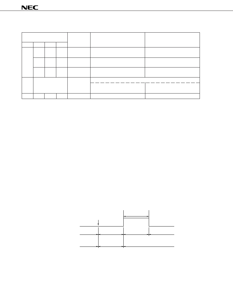
5.3 Standby Mode Release Timing
(1) STOP Mode Release Timing
Figure 5-1. STOP Mode Cancelation by Release Condition
Caution When a release condition is established in the STOP mode, the device is released from the STOP
mode, and goes into a wait state. At this time, if the release condition is not held, the device
goes into STOP mode again after the wait time has elapsed. Therefore, when releasing the STOP
mode, it is necessary to hold the release condition longer than the wait time.
Wait
(52/f
X
+
α
)
HALT mode
OPERATING
mode
STOP mode
Oscillation
stopped
Oscillation
OPERATING
mode
Oscillation
HALT instruction
(STOP mode)
Standby
release signal
Clock
α
: Oscillation growth time
相關(guān)PDF資料 |
PDF描述 |
|---|---|
| UPD6451AGT-301 | On-Screen Display Circuit |
| UPD6452CS-002 | On-Screen Display Circuit |
| UPD6452GT-102 | On-Screen Display Circuit |
| UPD6453 | UPD6453 Data Sheet | Data Sheet[11/1990] |
| UPD6453CY-001 | On-Screen Display Circuit |
相關(guān)代理商/技術(shù)參數(shù) |
參數(shù)描述 |
|---|---|
| UPD6451AGT-301 | 制造商:未知廠家 制造商全稱:未知廠家 功能描述:On-Screen Display Circuit |
| UPD6452CS-002 | 制造商:未知廠家 制造商全稱:未知廠家 功能描述:On-Screen Display Circuit |
| UPD6452GT-102 | 制造商:未知廠家 制造商全稱:未知廠家 功能描述:On-Screen Display Circuit |
| UPD6453 | 制造商:NEC 制造商全稱:NEC 功能描述:MOS INTEGRATED CIRCUIT CMOS LSI FOR 12 lines X 24 columns CHARACTER DISPLAY ON SCREEN |
| UPD6453CY | 制造商:NEC 制造商全稱:NEC 功能描述:MOS INTEGRATED CIRCUIT CMOS LSI FOR 12 lines X 24 columns CHARACTER DISPLAY ON SCREEN |
發(fā)布緊急采購(gòu),3分鐘左右您將得到回復(fù)。