- 您現(xiàn)在的位置:買賣IC網(wǎng) > PDF目錄300050 > ULQ-2/25-D24P (CD TECHNOLOGIES INC) 1-OUTPUT DC-DC REG PWR SUPPLY MODULE PDF資料下載
參數(shù)資料
| 型號: | ULQ-2/25-D24P |
| 廠商: | CD TECHNOLOGIES INC |
| 元件分類: | 電源模塊 |
| 英文描述: | 1-OUTPUT DC-DC REG PWR SUPPLY MODULE |
| 封裝: | 1.450 X 2.300 INCH, 0.350 INCH HEIGHT, QUARTER BRICK PACKAGE-8 |
| 文件頁數(shù): | 12/16頁 |
| 文件大?。?/td> | 566K |
| 代理商: | ULQ-2/25-D24P |
ULQ Models
8 - 2 5 A M P , S I N G L E O U T P U T C O N V E R T E R S
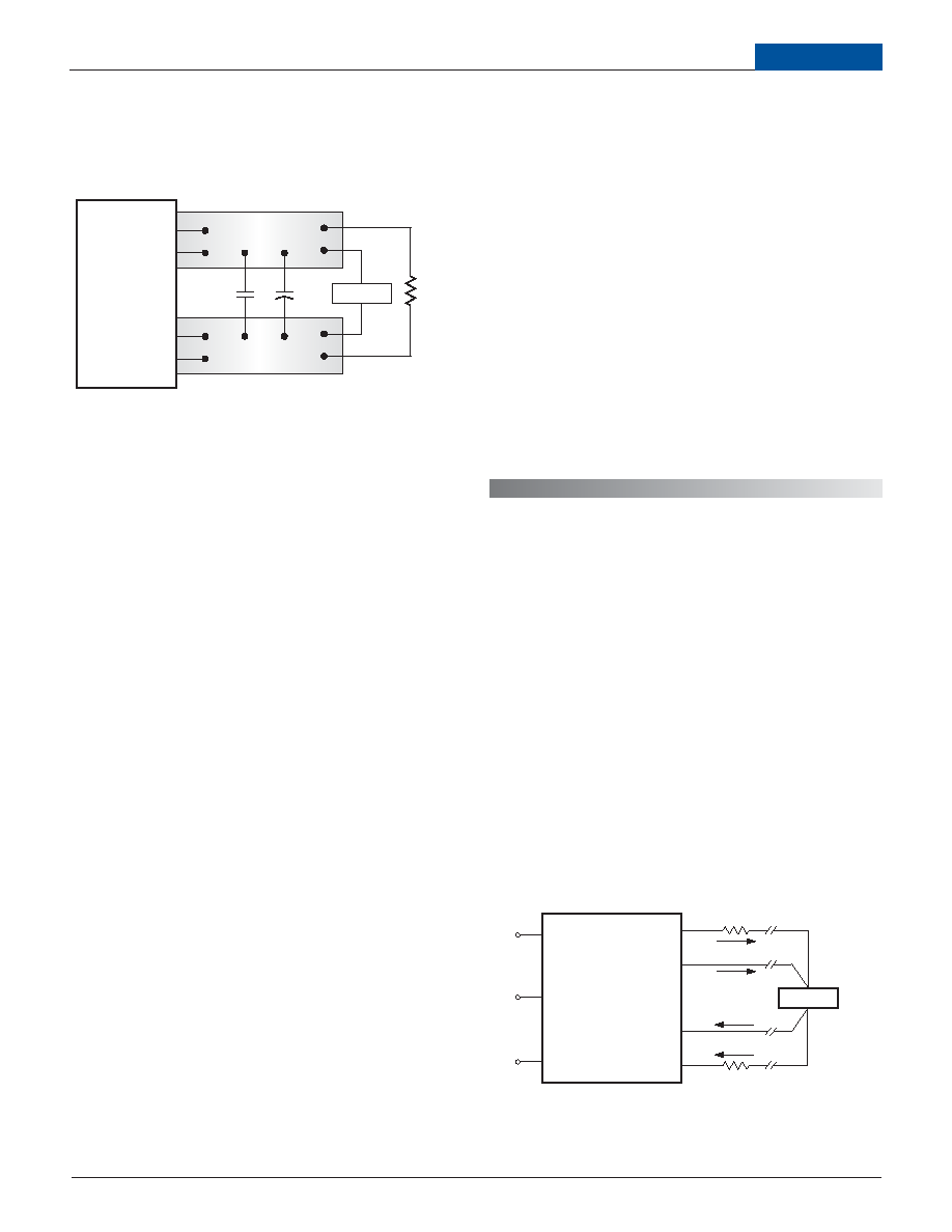
In Figure 3, the two copper strips simulate real-world pcb impedances
between the power supply and its load. In order to minimize measurement
errors, scope measurements should be made using BNC connectors, or the
probe ground should be less than inch and soldered directly to the xture.
C1
C1 = 0.1F CERAMIC
C2 = 10F TANTALUM
LOAD 2-3 INCHES (51-76mm) FROM MODULE
C2
RLOAD
7
8
COPPER STRIP
4
COPPER STRIP
SCOPE
+OUTPUT
–OUTPUT
+SENSE
–SENSE
Figure 3. Measuring Output Ripple/Noise (PARD)
Floating Outputs
Since these are isolated DC/DC converters, their outputs are "oating" with
respect to their input. Designers will normally use the –Output (pin 4) as the
ground/return of the load circuit.You can however, use the +Output (pin 8) as
ground/return to effectively reverse the output polarity.
Minimum Output Loading Requirements
ULQ converters employ a synchronous-rectier design topology and all
models regulate within spec and are stable under no-load to full load condi-
tions. Operation under no-load conditions however might slightly increase the
output ripple and noise.
Thermal Shutdown
The ULQ converters are equipped with thermal-shutdown circuitry. If envi-
ronmental conditions cause the temperature of the DC/DC converter to
rise above the designed operating temperature, a precision temperature
sensor will power down the unit. When the internal temperature decreases
below the threshold of the temperature sensor, the unit will self start. See
Performance/Functional Specications.
Output Overvoltage Protection
The ULQ output voltage is monitored for an overvoltage condition using a
comparator. The signal is optically coupled to the primary side and if the
output voltage rises to a level which could be damaging to the load, the sens-
ing circuitry will power down the PWM controller causing the output voltage
to decrease. Following a time-out period the PWM will restart, causing the
output voltage to ramp to its appropriate value. If the fault condition persists,
and the output voltage again climbs to excessive levels, the overvoltage
circuitry will initiate another shutdown cycle. This on/off cycling is referred to
as "hiccup" mode.
Current Limiting
As soon as the output current increases to approximately 130% of its rated
value, the DC/DC converter will go into a current-limiting mode. In this condi-
tion, the output voltage will decrease proportionately with increases in output
current, thereby maintaining somewhat constant power dissipation. This is
commonly referred to as power limiting. Current limit inception is dened
as the point at which the full-power output voltage falls below the specied
tolerance. See Performance/Functional Specications. If the load current,
being drawn from the converter, is signicant enough, the unit will go into a
short circuit condition as described below.
Short Circuit Condition
When a converter is in current-limit mode, the output voltage will drop as
the output current demand increases. If the output voltage drops too low, the
magnetically coupled voltage used to develop primary side voltages will also
drop, thereby shutting down the PWM controller. Following a time-out period,
the PWM will restart causing the output voltage to begin ramping to their
appropriate value. If the short-circuit condition persists, another shutdown
cycle will be initiated. This on/off cycling is referred to as "hiccup" mode.
The hiccup cycling reduces the average output current, thereby preventing
internal temperatures from rising to excessive levels. The ULQ Series is
capable of enduring an indenite short circuit output condition.
5
LOAD
+OUTPUT
–INPUT
Sense Current
Contact and PCB resistance
losses due to IR drops
Contact and PCB resistance
losses due to IR drops
Sense Return
+INPUT
ON/OFF
CONTROL
TRIM
+SENSE
–OUTPUT
–SENSE
4
5
1
3
6
8
IOUT Return
IOUT
7
2
Remote Sense
Note: The Sense and VOUT lines are internally connected through low-value
resistors. Nevertheless, if the sense function is not used for remote regulation
the user should connect the +Sense to +VOUT and -Sense to –VOUT at the
DC/DC converter pins.
ULQ series converters employ a sense feature to provide point of use regula-
tion, thereby overcoming moderate IR drops in pcb conductors or cabling.
The remote sense lines carry very little current and therefore require minimal
cross-sectional-area conductors. The sense lines, which are capacitively
coupled to their respective output lines, are used by the feedback control-loop
to regulate the output. As such, they are not low impedance points and must
be treated with care in layouts and cabling. Sense lines on a pcb should be
run adjacent to dc signals, preferably ground. In cables and discrete wiring
applications, twisted pair or other techniques should be implemented.
ULQ series converters will compensate for drops between the output voltage
at the DC/DC and the sense voltage at the DC/DC provided that:
[VOUT(+) –VOUT(–)] – [Sense(+) –Sense (–)]
≤ 10% VOUT
Figure 4. Remote Sense Circuit Conguration
F E A T U R E S A N D O P T I O N S
相關(guān)PDF資料 |
PDF描述 |
|---|---|
| ULQ-3.3/20-D24NL1 | 1-OUTPUT DC-DC REG PWR SUPPLY MODULE |
| UM-LR-PC | CONNECTOR ACCESSORY |
| UM-PR-PC | CONNECTOR ACCESSORY |
| UM-QA-JJ | CONNECTOR ACCESSORY |
| UM-QLP-1.5-6 | CONNECTOR ACCESSORY |
相關(guān)代理商/技術(shù)參數(shù) |
參數(shù)描述 |
|---|---|
| ULQ2436M | 制造商:ALLEGRO 制造商全稱:Allegro MicroSystems 功能描述:COUNTDOWN POWER TIMER |
| ULQ2460A | 制造商:ALLEGRO 制造商全稱:Allegro MicroSystems 功能描述:ELECTRONIC IGNITION TIMING |
| ULQ2460C | 制造商:ALLEGRO 制造商全稱:Allegro MicroSystems 功能描述:ELECTRONIC IGNITION TIMING |
| ULQ2460LW | 制造商:Allegro MicroSystems LLC 功能描述: |
| ULQ2470L | 制造商:未知廠家 制造商全稱:未知廠家 功能描述:BUS DRIVER / RECEIVER |
發(fā)布緊急采購,3分鐘左右您將得到回復(fù)。