- 您現(xiàn)在的位置:買賣IC網(wǎng) > PDF目錄359308 > UET0J470MHD (Nichicon Corporation) ALUMINUM ELECTROLYTIC CAPACITORS PDF資料下載
參數(shù)資料
| 型號: | UET0J470MHD |
| 廠商: | Nichicon Corporation |
| 英文描述: | ALUMINUM ELECTROLYTIC CAPACITORS |
| 中文描述: | 鋁電解電容器 |
| 文件頁數(shù): | 1/1頁 |
| 文件大小: | 72K |
| 代理商: | UET0J470MHD |
U
1
E
2
T
3
1
4
A
5
4
6
7
7
0
8
M
9
E
10
D
11
Configuration
Capacitance tolerance (±20%)
Rated Capacitance (47
m
F)
Rated voltage (10V)
Series name
Type
P
0
f
D
P
f
d
5
2.0
0.5
6.3
2.5
0.5
8
3.5
0.6
10
5.0
0.6
12.5
5.0
0.6
16
7.5
0.8
L+
MAX
(L < 20) 1.5
(L
20) 2.0
f
D
5
Pb-free leadwire
Pb-free PET sleeve
DD
6.3
ED
8 á 10
PD
12.5
á
16
HD
Configuration
(mm)
15
MIN
4
MIN
f
D
0
f
d
Sleeve (P.E.T.)
Pressure
(
f
6.3up)
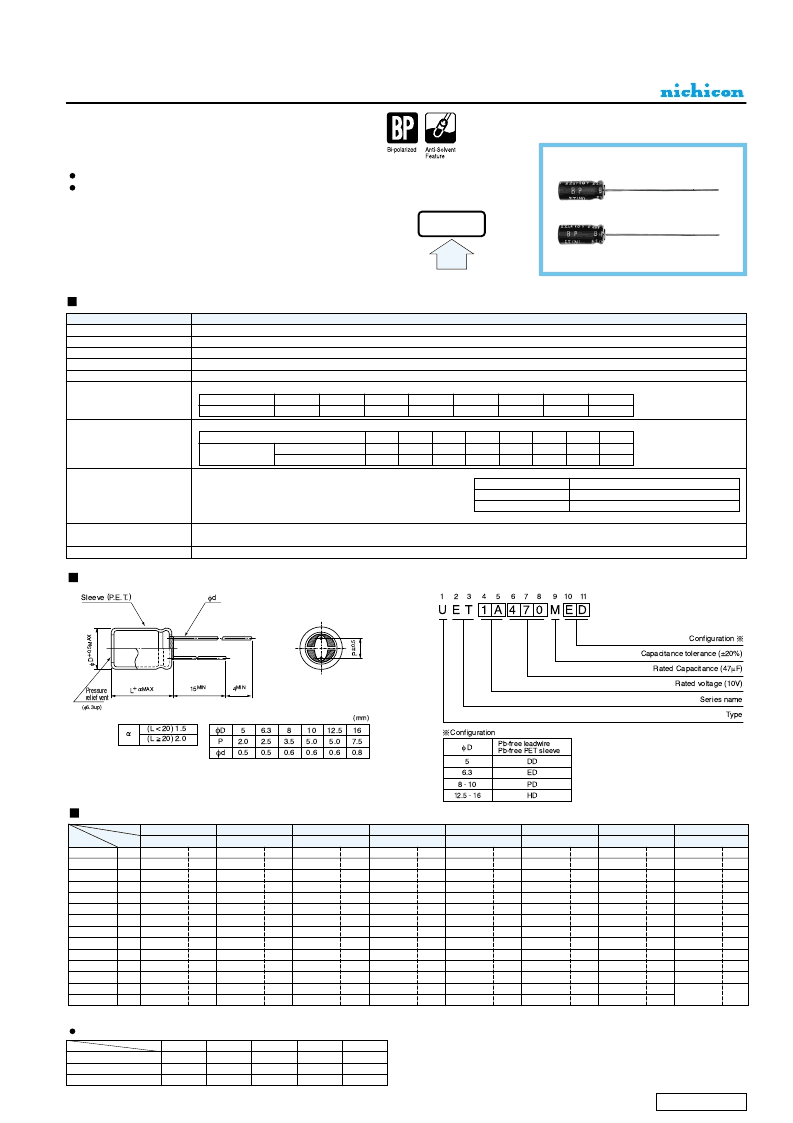
ALUMINUM ELECTROLYTIC CAPACITORS
ET
series
Bi-Polarized, Wide Temperature Range
Bi-polarized series for operations over wide temperature range of
–
55 ~ +105
°
C
.
Adapted to the RoHS directive (2002/95/EC).
Radial Lead Type
Type numbering system (Example : 10V 47
μ
F)
Specifications
Category Temperature Range
Rated Voltage Range
Rated Capacitance Range
Capacitance Tolerance
Leakage Current
tan
δ
Stability at Low Temperature
Endurance
Shelf Life
Marking
Performance Characteristics
Item
–
55 ~ +105
°
C
6.3 ~ 100V
0.47 ~ 1000μF
±20% at 120Hz, 20
°
C
After 5 minutes' application of rated voltage, leakage current is not more than 0.03CV or 3 (μA), whichever is greater.
Measurement frequency : 120Hz, Temperature : 20
°
C
Rated voltage (V)
tan
δ
(MAX.)
0.24
0.20
0.16
0.16
Printed with white color letter on black sleeve.
Measurement frequency : 120Hz
35
2
3
3
After 1000 hours' application of rated voltage at 105
°
C with the
polarity inverted every 250 hours, capacitors meet the
characteristic requirement listed at right.
After storing the capacitors under no load at 105
°
C for 1000 hours, and after performing voltage treatment based on JIS C 5101-4
clause 4.1 at 20
°
C, they will meet the specified value for endurance characteristics listed above.
E T
V P
6.3
10
16
25
35
0.14
50
0.12
63
0.10
100
0.09
Z
–
25
°
C / Z+20
°
C
Z
–
40
°
C / Z+20
°
C
Rated voltage (V)
Impedance ratio
ZT / Z20 (MAX.)
6.3
4
8
10
3
6
16
2
4
25
2
4
50
2
63
2
3
100
2
3
High
Temperature
Leakage current
tan
δ
Capacitance change
Within ±20% of initial value
200% or less of initial specified value
Initial specified value or less
Please refer to page 21, 22, 23 about the formed or taped product spec.
Please refer to page 3 for the minimum order quantity.
Frequency coefficient of rated ripple current
50 Hz
0.75
0.80
0.85
Cap.(μF)
0000
~ 47
00
0
100 ~ 470
0
1000
120 Hz
1.00
1.00
1.00
300 Hz
1.35
1.23
1.10
1 kHz
1.57
1.34
1.13
10 kHz ~
2.00
1.50
1.15
Frequency
5
×
11
5
×
11
6.3
×
11
8
×
11.5
8
×
11.5
10
×
12.5
10
×
20
12.5
×
20
12.5
×
25
16
×
25
42
57
67
125
204
275
371
668
5
×
11
5
×
11
5
×
11
5
×
11
6.3
×
11
8
×
11.5
10
×
12.5
10
×
16
10
×
20
12.5
×
25
16
×
25
16
×
31.5
10
15
22
32
39
64
114
164
200
304
Rated
ripple
26
31
53
96
129
157
275
486
8
12
18
22
29
51
82
107
146
264
443
593
25
40
68
89
111
196
364
493
586
30
51
63
89
139
279
346
460
746
5
×
11
6.3
×
11
6.3
×
11
10
×
12.5
10
×
16
10
×
20
12.5
×
20
16
×
25
0.47
1
2.2
3.3
4.7
10
22
33
47
100
220
330
470
1000
Dimensions
R47
010
2R2
3R3
4R7
100
220
330
470
101
221
331
471
102
5
×
11
6.3
×
11
8
×
11.5
10
×
12.5
10
×
16
10
×
20
12.5
×
25
46
61
104
168
229
300
550
0J
Rated Ripple (mArms) at 105
°
C 120Hz
6.3
1A
10
1C
16
1E
25
1V
35
1H
50
1J
2A
63
100
5
×
11
6.3
×
11
6.3
×
11
8
×
11.5
10
×
12.5
10
×
20
12.5
×
20
12.5
×
25
16
×
25
5
×
11
6.3
×
11
8
×
11.5
10
×
12.5
10
×
12.5
10
×
20
12.5
×
25
16
×
25
16
×
25
6.3
×
11
6.3
×
11
8
×
11.5
10
×
16
10
×
20
10
×
20
12.5
×
25
16
×
31.5
5
×
11
5
×
11
6.3
×
11
8
×
11.5
10
×
12.5
10
×
16
12.5
×
25
12.5
×
25
16
×
25
16
×
31.5
23
34
55
79
100
164
336
414
543
871
Case size
φ
D
×
L (mm)
V
Code
Cap.(μF)
Please refer to page 21 about the end seal configulation.
CAT.8100V
相關(guān)PDF資料 |
PDF描述 |
|---|---|
| UFG1A471MHM | Dual Inverter |
| UFW1C332MPD | ALUMINUM ELECTROLYTIC CAPACITORS |
| UG4JL-AL5-0-R | EMITTER COMMON (DUAL DIGITAL TRANSISTORS) |
| UG8J-AL5-0-R | EMITTER COMMON (DUAL DIGITAL TRANSISTORS) |
| UH276 | COMPLEMENTARY OUTPUTS HALL EFFECT LATCH IC |
相關(guān)代理商/技術(shù)參數(shù) |
參數(shù)描述 |
|---|---|
| UET0J470MPD | 制造商:NICHICON 制造商全稱:Nichicon corporation 功能描述:ALUMINUM ELECTROLYTIC CAPACITORS |
| UET0J471MDD | 制造商:NICHICON 制造商全稱:Nichicon corporation 功能描述:ALUMINUM ELECTROLYTIC CAPACITORS |
| UET0J471MED | 制造商:NICHICON 制造商全稱:Nichicon corporation 功能描述:ALUMINUM ELECTROLYTIC CAPACITORS |
| UET0J471MHD | 制造商:NICHICON 制造商全稱:Nichicon corporation 功能描述:ALUMINUM ELECTROLYTIC CAPACITORS |
| UET0J471MPD | 功能描述:鋁質(zhì)電解電容器 - 帶引線 6.3volts 470uF 10x20 20% 5LS RoHS:否 制造商:Kemet 引線類型: 電容:220 uF 容差:20 % 電壓額定值:25 V 工作溫度范圍: 端接類型:Radial 外殼直徑:8 mm 外殼長度:11 mm 引線間隔:5 mm 產(chǎn)品:General Purpose Electrolytic Capacitors 封裝:Bulk |
發(fā)布緊急采購,3分鐘左右您將得到回復(fù)。