- 您現(xiàn)在的位置:買賣IC網(wǎng) > PDF目錄378722 > UC1584 (Texas Instruments, Inc.) Secondary Side Synchronous Post Regulator PDF資料下載
參數(shù)資料
| 型號: | UC1584 |
| 廠商: | Texas Instruments, Inc. |
| 英文描述: | Secondary Side Synchronous Post Regulator |
| 中文描述: | 二次側同步后穩(wěn)壓器 |
| 文件頁數(shù): | 5/7頁 |
| 文件大?。?/td> | 153K |
| 代理商: | UC1584 |

5
UC1584
UC2584
UC3584
Edge Modulation
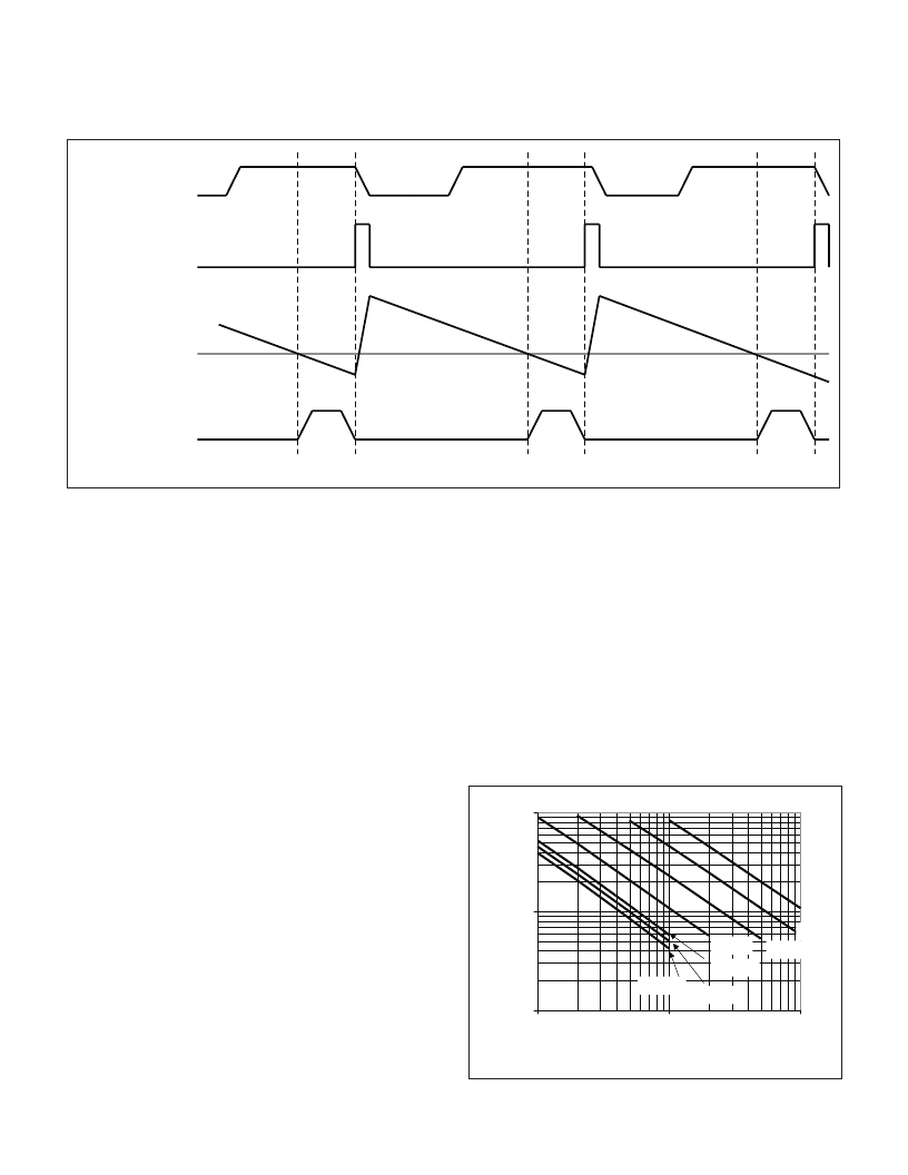
During normal operation the oscillator must be synchro-
nized to the falling edge of the transformer secondary
waveform. Synchronization is achieved by connecting
SYNC to the secondary winding via a resistor divider.
The resistor divider must be chosen to provide a SYNC
pin voltage in excess of 1V at the lowest operating volt-
age on the transformer secondary winding. The UC3584
will generate a narrow internal synchronization pulse
which will synchronize the oscillator to the switching fre-
quency of the main converter.
PWM and Output Driver
The UC3584 employs leading edge modulation tech-
nique to set the required on time of its output. Leading
edge modulation is preferred for secondary side regula-
tion in multiple output converters to prevent ambiguity in
the primary current waveform. In fact, this is the only fea-
sible technique to preserve compatibility with primary
side peak current mode control.
As Fig. 1 depicts the UC3584 utilizes voltage mode con-
trol to regulate output voltage. The output pulse width
(the on-time of the MOSFET switch) is determined on a
cycle-by-cycle basis by comparing the output of the volt-
age error amplifier and the ramp waveforms across the
timing capacitor. OUT is asserted when the voltage on
COMP exceeds the voltage on CT. There are three more
conditions which must be satisfied to obtain an active
high on the OUT pin. These conditions are:
1. VCC within normal range (UVLO is inactive),
2. No fault condition is detected,
3. C
T
is discharging.
During the fast charging time of the C
T
capacitor is held
low.
Ultimately, the output of the PWM circuitry controls the
conduction interval of an external N-channel MOSFET
switch in the power supply. The UC3584 employs an
on-board, floating gate driver circuit to interface to the
external switch. An external capacitor connected be-
tween VFLT and SRC acts as a floating power supply for
V
SEC
C
T
OUT
COMP
INTERNAL
SYNC PULSE
Figure 1. Trailing edge synchronization, leading edge modulation.
APPLICATION INFORMATION (cont.)
UDG-99064
1.E+04
1.E+05
1.E+06
1.E+03
1.E+04
1.E+05
TIMING RESISTOR (Ohms)
F
47pF
100pF
220pF
470pF
1000pF
1200pF
1500pF
Figure 2. Oscillator frequency vs. R
T
with C
T
as a
parameter.
相關PDF資料 |
PDF描述 |
|---|---|
| UC2854AJ | ADVANCED HIGH-POWER FACTOR PREREGULATOR |
| UC2854AQ | ADVANCED HIGH-POWER FACTOR PREREGULATOR |
| UC2854AL | OMNIFET II: FULLY AUTOPROTECTED POWER MOSFET |
| UC2854AQTR | Power Factor Controller |
| UC2854BL | Analog IC |
相關代理商/技術參數(shù) |
參數(shù)描述 |
|---|---|
| UC1584J | 制造商:未知廠家 制造商全稱:未知廠家 功能描述:Analog IC |
| UC-1602ASWCG01 | 制造商:WISECHIP SEMICONDUCTOR INC 功能描述:2.26" 16 x 2 Parallel/I2C/Serial White OLED LCD 制造商:WISECHIP SEMICONDUCTOR INC 功能描述:2.26" 16x2 White OLED LCD |
| UC-1602ASYCG01 | 制造商:WISECHIP SEMICONDUCTOR INC 功能描述:2.26" (16 x 2) Yellow OLED LCD (68.50 17.50 2.00) 制造商:WISECHIP SEMICONDUCTOR INC 功能描述:2.26" 16x2 Yellow OLED LCD |
| UC1602I | 制造商:未知廠家 制造商全稱:未知廠家 功能描述:65x102 Matrix LCD Controller-Driver |
| UC1606 | 制造商:未知廠家 制造商全稱:未知廠家 功能描述:65COM x 132SEG Matrix LCD Controller-Driver |
發(fā)布緊急采購,3分鐘左右您將得到回復。