- 您現(xiàn)在的位置:買(mǎi)賣(mài)IC網(wǎng) > PDF目錄300049 > UA78L02ACLPE3 (TEXAS INSTRUMENTS INC) 2.6 V FIXED POSITIVE REGULATOR, PBCY3 PDF資料下載
參數(shù)資料
| 型號(hào): | UA78L02ACLPE3 |
| 廠商: | TEXAS INSTRUMENTS INC |
| 元件分類(lèi): | 固定正電壓?jiǎn)温份敵鰳?biāo)準(zhǔn)穩(wěn)壓器 |
| 英文描述: | 2.6 V FIXED POSITIVE REGULATOR, PBCY3 |
| 封裝: | ROHS COMPLIANT, PLASTIC, TO-226AA, TO-92, 3 PIN |
| 文件頁(yè)數(shù): | 25/27頁(yè) |
| 文件大?。?/td> | 702K |
| 代理商: | UA78L02ACLPE3 |
第1頁(yè)第2頁(yè)第3頁(yè)第4頁(yè)第5頁(yè)第6頁(yè)第7頁(yè)第8頁(yè)第9頁(yè)第10頁(yè)第11頁(yè)第12頁(yè)第13頁(yè)第14頁(yè)第15頁(yè)第16頁(yè)第17頁(yè)第18頁(yè)第19頁(yè)第20頁(yè)第21頁(yè)第22頁(yè)第23頁(yè)第24頁(yè)當(dāng)前第25頁(yè)第26頁(yè)第27頁(yè)
A78L00 SERIES
POSITIVE-VOLTAGE REGULATORS
SLVS010S JANUARY 1976 REVISED FEBRUARY 2004
7
POST OFFICE BOX 655303
DALLAS, TEXAS 75265
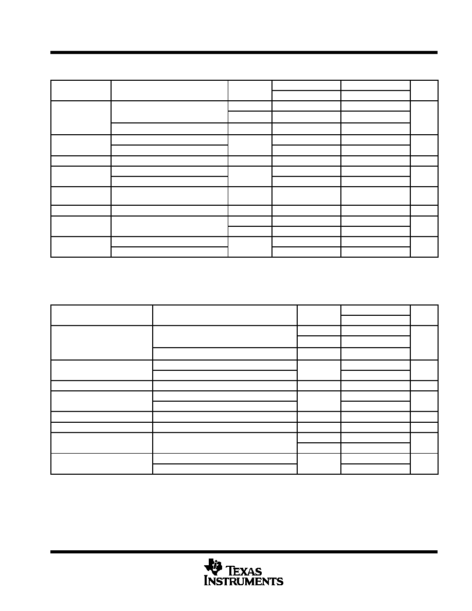
electrical characteristics at specified virtual junction temperature, VI = 16 V, IO = 40 mA (unless
otherwise noted)
PARAMETER
TEST CONDITIONS
T
A78L09C
A78L09AC
UNIT
PARAMETER
TEST CONDITIONS
TJ
MIN
TYP
MAX
MIN
TYP
MAX
UNIT
V
12Vt 24 V
I
1A t 40A
25
°C
8.3
9
9.7
8.6
9
9.4
Output voltage
VI = 12 V to 24 V,
IO = 1 mA to 40 mA
0
°C to 125°C
8.1
9.9
8.55
9.45
V
Output voltage
IO = 1 mA to 70 mA
0
°C to 125°C
8.1
9.9
8.55
9.45
V
Input
VI = 12 V to 24 V
25
°C
45
225
45
175
mV
Input
voltage regulation
VI = 13 V to 24 V
25
°C
40
175
40
125
mV
Ripple rejection
VI = 15 V to 25 V,
f = 120 Hz
25
°C
36
45
38
45
dB
Output
IO = 1 mA to 100 mA
25
°C
19
90
19
90
mV
Output
voltage regulation
IO = 1 mA to 40 mA
25
°C
11
40
11
40
mV
Output
noise voltage
f = 10 Hz to 100 kHz
25
°C
58
V
Dropout voltage
25
°C
1.7
V
Bias current
25
°C
4.1
6
4.1
6
mA
Bias current
125
°C
5.5
mA
Bias
VI = 13 V to 24 V
0
°C to 125°C
1.5
mA
Bias
current change
IO = 1 mA to 40 mA
0
°C to 125°C
0.2
0.1
mA
Pulse-testing techniques maintain TJ as close to TA as possible. Thermal effects must be taken into account separately. All characteristics are
measured with a 0.33-
F capacitor across the input and a 0.1-F capacitor across the output.
electrical characteristics at specified virtual junction temperature, VI = 14 V, IO = 40 mA (unless
otherwise noted)
PARAMETER
TEST CONDITIONS
T
A78L10AC
UNIT
PARAMETER
TEST CONDITIONS
TJ
MIN
TYP
MAX
UNIT
V
13Vt 25 V
I
1A t 40A
25
°C
9.6
10
10.4
Output voltage
VI = 13 V to 25 V,
IO = 1 mA to 40 mA
0
°C to 125°C
9.5
10.5
V
Output voltage
IO = 1 mA to 70 mA
0
°C to 125°C
9.5
10.5
V
Input voltage regulation
VI = 13 V to 25 V
25
°C
51
175
mV
Input voltage regulation
VI = 14 V to 25 V
25
°C
42
125
mV
Ripple rejection
VI = 15 V to 25 V,
f = 120 Hz
25
°C
37
44
dB
Output voltage regulation
IO = 1 mA to 100 mA
25
°C
20
90
mV
Output voltage regulation
IO = 1 mA to 40 mA
25
°C
11
40
mV
Output noise voltage
f = 10 Hz to 100 kHz
25
°C
62
V
Dropout voltage
25
°C
1.7
V
Bias current
25
°C
4.2
6
mA
Bias current
125
°C
5.5
mA
Bias current change
VI = 14 V to 25 V
0
°Cto125°C
1.5
mA
Bias current change
IO = 1 mA to 40 mA
0
°C to 125°C
0.1
mA
Pulse-testing techniques maintain TJ as close to TA as possible. Thermal effects must be taken into account separately. All characteristics are
measured with a 0.33-
F capacitor across the input and a 0.1-F capacitor across the output.
相關(guān)PDF資料 |
PDF描述 |
|---|---|
| UA78L10ACDG4 | 10 V FIXED POSITIVE REGULATOR, PDSO8 |
| UA78L10ACDRG4 | 10 V FIXED POSITIVE REGULATOR, PDSO8 |
| UA78L10ACLPE3 | 10 V FIXED POSITIVE REGULATOR, PBCY3 |
| UA78L10ACLPRE3 | 10 V FIXED POSITIVE REGULATOR, PBCY3 |
| UA78L02ACDG4 | 2.6 V FIXED POSITIVE REGULATOR, PDSO8 |
相關(guān)代理商/技術(shù)參數(shù) |
參數(shù)描述 |
|---|---|
| UA78L02ACLPR | 制造商:未知廠家 制造商全稱:未知廠家 功能描述:VOLT REGULATOR|FIXED|+2.6V|BIPOLAR|SIP|3PIN|PLASTIC |
| UA78L02CD | 制造商:TI 制造商全稱:Texas Instruments 功能描述:POSITIVE-VOLTAGE REGULATORS |
| UA78L02CDR | 制造商:未知廠家 制造商全稱:未知廠家 功能描述:Positive Fixed Voltage Regulator |
| UA78L02CLP | 制造商:TI 制造商全稱:Texas Instruments 功能描述:POSITIVE-VOLTAGE REGULATORS |
| UA78L05A | 制造商:未知廠家 制造商全稱:未知廠家 功能描述:5V. 100mA Fixed Positive Voltage Regulator |
發(fā)布緊急采購(gòu),3分鐘左右您將得到回復(fù)。