- 您現(xiàn)在的位置:買賣IC網(wǎng) > PDF目錄382711 > U840B Digital / Wipe-Wash Control for Rear or Front Wiper PDF資料下載
參數(shù)資料
| 型號: | U840B |
| 英文描述: | Digital / Wipe-Wash Control for Rear or Front Wiper |
| 中文描述: | 數(shù)字/擦拭為前清洗后或控制雨刷 |
| 文件頁數(shù): | 2/8頁 |
| 文件大小: | 169K |
| 代理商: | U840B |

U840B
TELEFUNKEN Semiconductors
Rev. A2, 03-Feb-97
2 (8)
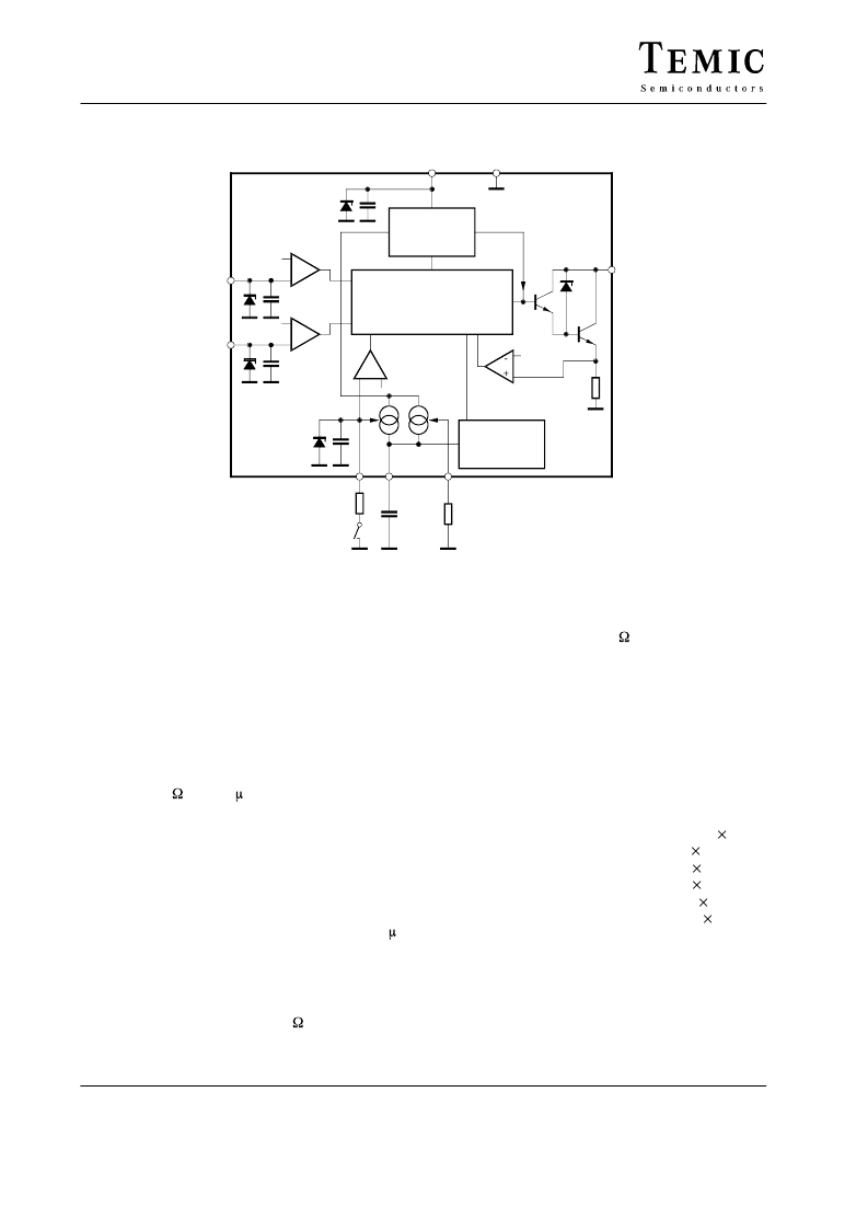
Block Diagram
Stabilization
POR
Load-dump –
detection
+
–
+
–
Shunt
Logic
Interval
comparator
CP–
comparator
PP–
comparator
Short-circuit
comparator
Oscillator
PP
WASH
VS
GND
OUT
INT
C
R
1.2 k
1
μ
F
47 k
13285
+ –
Figure 1. Block Diagram
Circuit Description
Power Supply
For reasons of interference protection and surge
immunity, all circuits must be provided with an
RC-circuit for current limitation in the event of
overvoltages and for buffering in the event of voltage dips
at V
S
.
Suggested dimensioning:
R
4
= l80 C
1
= 47 F, refer to figure 2.
Between V
S
and GND there is an integrated 14 V Z-diode.
The operation voltage is between V
Batt
= 9 to 16 V.
The capacitor can be dimensioned smaller, if is used in the
supply for a diode quad for polarity independence. In this
case, there is no discharging through R
4
in the event of
negative interference pulses, but only a discharging from
the self current input of the circuit. Typical value: 10 F.
Oscillator
In the circuit all timing sequences are derived from an RC
oscillator which is charged by an internal current source
and discharged by an integrated 500- resistor. The basic
frequency f
0
is determined by the resistor RO between
Pin RO and GND and by the capacitance CO between
Pin CO and GND. The basic frequency is adjusted to
320 Hz (3.125 ms) by R
6
= 39 k and C
2
= l00 nF.
The tolerances and the temperature coefficients of the
external devices determine the precision of the oscillator
frequency. A metallic-film resistor
±
l% and a capacitance
±
5% with a TC of a MKT or MKS2 capacitance is
suggested.
The debouncing time t
1
, the turn-on time of the relay t
2
,
the delay time t
4
, the dry wiping time t
5
and the
debouncing time t
6
(short circuit detection) depend on the
oscillator frequency f
0
as follows:
Debouncing time INT, CP
Turn-on time relay
Interval pause
Delay time wipe/wash mode
Dry wiping time
Debouncing time SC
t
1
= 24 to 32
t
2
= 120
t
3
= 296
t
4
= 256
t
5
= 1184
t
6
= 2 to
3
l/f
0
l/f
0
1/f
int
l/f
0
l/f
0
1/f
0
SC (short circuit) = collector current of relay driver
I
C
> 500 mA.
The clock counts of the debouncing times are not fixed
because the switching of the signals and the system clock
are asynchronous. The cause of the clock count variation
is shown by the example of the short circuit debouncing
(figure 2).
相關(guān)PDF資料 |
PDF描述 |
|---|---|
| U840B-FP | Digital / Wipe-Wash Control for Rear or Front Wiper |
| U846B | Output rail-to-rail operational amplifiers |
| U846B-FP | Output rail-to-rail operational amplifiers |
| U8600B | Rail-to-rail high output current single operational amplifier |
| U8601B-B | Rail-to-rail high output current single operational amplifier |
相關(guān)代理商/技術(shù)參數(shù) |
參數(shù)描述 |
|---|---|
| U840B-FP | 制造商:TEMIC 制造商全稱:TEMIC Semiconductors 功能描述:Digital / Wipe-Wash Control for Rear or Front Wiper |
| U841SH9V7GE | 制造商:C&K Components 功能描述: |
| U842 | 功能描述:開關(guān)配件 Hex Nut 10mm RoHS:否 制造商:C&K Components 類型:Cap 用于:Pushbutton Switches 設(shè)計(jì)目的: |
| U842B | 制造商:TEMIC 制造商全稱:TEMIC Semiconductors 功能描述:Wiper Control for Intermittent and Wipe/ Wash Mode |
| U842B-FP | 制造商:TEMIC 制造商全稱:TEMIC Semiconductors 功能描述:Wiper Control for Intermittent and Wipe/ Wash Mode |
發(fā)布緊急采購,3分鐘左右您將得到回復(fù)。