- 您現(xiàn)在的位置:買賣IC網(wǎng) > PDF目錄199513 > TV26RS (AMPHENOL CORP) STAINLESS STEEL, FEMALE; MALE, MIL SERIES CONNECTOR, CRIMP, PLUG PDF資料下載
參數(shù)資料
| 型號: | TV26RS |
| 廠商: | AMPHENOL CORP |
| 元件分類: | MIL系列連接器 |
| 英文描述: | STAINLESS STEEL, FEMALE; MALE, MIL SERIES CONNECTOR, CRIMP, PLUG |
| 文件頁數(shù): | 1/1頁 |
| 文件大小: | 36K |
| 代理商: | TV26RS |
19
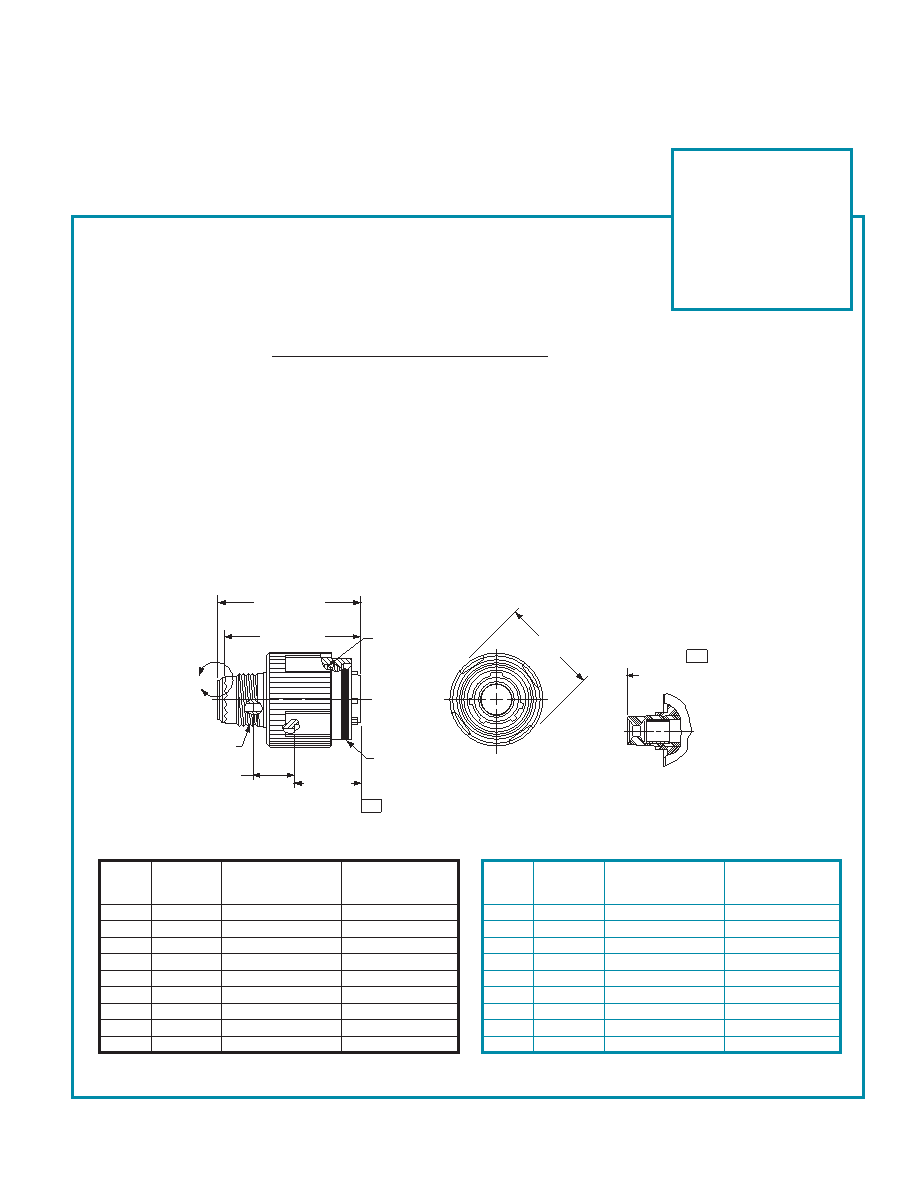
TV26/MTV26 – crimp, metal
CLUTCH-LOK straight plug for high vibration
and harsh environment applications
The latest in MIL-DTL-38999, Series III Connector Technology is the CLUTCH-LOK. Designed
for high vibration and harsh environments such as aircraft gas turbine engines, it is also an
ideal choice for demanding applications such as aircraft, space and military ground vehicles.
The unique clutch design of the Amphenol CLUTCH-LOK means that you don’t have to
compromise the need for quick, smooth mating of plugs and receptacles in order to get
increased uncoupling torque.
The CLUTCH-LOK has proven to not only remain mated and pass all the Series III specifica-
tion requirements - it also has proven to actually tighten itself under vibration. This is a
powerful advantage over the traditionally high vibration application connectors. The CLUTCH-
LOK is also a tremendous advantage in inaccessible, hard to reach areas where mating
torque is difficult to apply and complete coupling is not verifiable by inspection.
CLUTCH-LOK features and benefits:
High degree of differential torque
Infinite free coupling and positive metal-to-metal bottoming with each mating
No settling back to the next ratchet tooth
Available with stainless steel shells and Class K firewall inserts
All the advantages of MIL-DTL-38999 Series III including EMI/RFI shielding, electrolytic erosion
resistance and contact protection with recessed pins
Enhanced connector performance at affordable prices
Completely intermateable with all existing MIL-DTL-38999 Series III connectors
Fully QPL’d
Part number reference.
See how to order, pages 43, 44
to complete.
TV26RKXXXXX
TV26RSXXXXX
For parts with MS Stamping
use MTV26( ) part number as
follow:
MTV26RKXXXXX
MTV26RSXXXXX
MS
B Thread
Q
Shell
Shell Size
0.1P-0.3L-TS-2B
Dia.
Size
Code
(Plated)
Max.
9
A
.6250
.858
11
B
.7500
.984
13
C
.8750
1.157
15
D
1.0000
1.280
17
E
1.1875
1.406
19
F
1.2500
1.516
21
G
1.3750
1.642
23
H
1.5000
1.768
25
J
1.6250
1.890
Blue band indicates rear release contact retention system
All dimensions for reference only.
MS
V
Shell
Shell Size
Q
Thread
Size
Code
Max.
Metric
9
A
21.8
M12X1-6g
11
B
25.0
M15X1-6g
13
C
29.4
M18X1-6g
15
D
32.5
M22X1-6g
17
E
35.7
M25X1-6g
19
F
38.5
M28X1-6g
21
G
41.7
M31X1-6g
23
H
44.9
M34X1-6g
25
J
48.0
M37X1-6g
Inches
Millimeters
1.234 MAX
31.34 MAX
1.220 MAX
31.00 MAX
B THREAD
D
V THREAD
.359 MAX
9.12 MAX
.591 +.003
–.000
15.01 +.08
–.00
BLUE BAND
Q
1.656 MAX
42.06 MAX
VIEW D
FOR SIZE 8 COAXIAL ONLY,
RELATIVE TO –A–
–A–
相關PDF資料 |
PDF描述 |
|---|---|
| TV79BAGCACAC25.000 | TCVCXO, SINE OUTPUT, 25 MHz |
| TV79BAGBDCBDFREQ | TCVCXO, SINE OUTPUT, 0.625 MHz - 52 MHz |
| TV79BAGCACEC25.000 | TCVCXO, SINE OUTPUT, 25 MHz |
| TV79BAGCBBCD25.000 | TCVCXO, CLIPPED SINE OUTPUT, 25 MHz |
| TV79BAGCBBEDFREQ | TCVCXO, CLIPPED SINE OUTPUT, 0.625 MHz - 52 MHz |
相關代理商/技術參數(shù) |
參數(shù)描述 |
|---|---|
| TV270VC/A | 制造商:Promise Technologies 功能描述:VTRAK E-CLASS SINGLE-CONTROLLER (4) 1TB SATA HDDS - Bulk |
| TV2713D-IR | 制造商:Hikvision USA 功能描述:Lens, IR Varifocal 2.7~13mmDc Auto IRis, 1/3In Format 制造商:HIKVISION 功能描述:LENS, IR VARIFOCAL 2.7-13MM DC AUTO IRIS, 1/3IN FORMAT |
| TV272VC/A | 制造商:Promise Technologies 功能描述:VTRAK E-CLASS 3U/16-BAY DUAL-CONTROLLER (8) 1TB SATA HDDS - Bulk |
| TV274VC/A | 制造商:Promise Technologies 功能描述:VTRAK J-CLASS 3U/16-BAY DUAL-CONTROLLER (16) 1TB SATA HDDS - Bulk |
| TV276ZM/A | 制造商:Promise Technologies 功能描述:APPLE VTRAK E-CLASS SUBSYSTEM SERVICE PARTS KIT - Bulk |
發(fā)布緊急采購,3分鐘左右您將得到回復。