- 您現(xiàn)在的位置:買賣IC網(wǎng) > PDF目錄373738 > TSL2550T (TAOS Inc.) AMBIENT LIGHT SENSOR WITH SMBus INTERFACE PDF資料下載
參數(shù)資料
| 型號: | TSL2550T |
| 廠商: | TAOS Inc. |
| 英文描述: | AMBIENT LIGHT SENSOR WITH SMBus INTERFACE |
| 中文描述: | 常溫與SMBus接口光傳感器 |
| 文件頁數(shù): | 8/20頁 |
| 文件大?。?/td> | 280K |
| 代理商: | TSL2550T |
TSL2550
AMBIENT LIGHT SENSOR
WITH SMBus INTERFACE
TAOS029L
OCTOBER 2007
8
Copyright 2007, TAOS Inc.
The
LUMENOLOGY
Company
www.taosinc.com
Command Register
The command register is used primarily to:
Select which ADC register will be read during a read cycle
Switch the dynamic range of the device between standard and extended range modes
Power the device up for operation or power it down for minimum power consumption
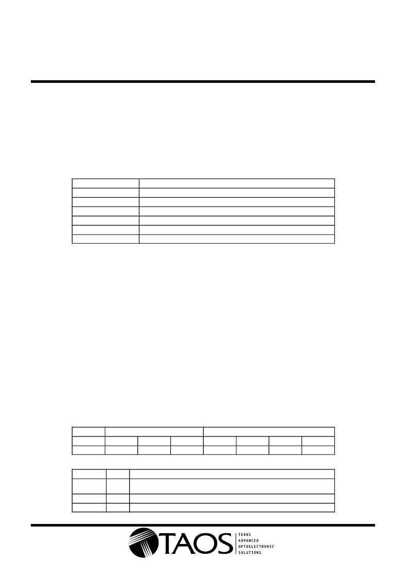
Table 1 shows the six primary commands used to control the TSL2550.
Table 1. Command Summary
COMMAND
0x00h
0x03h
0x1Dh
0x18h
0x43h
0x83h
FUNCTION
Power-down state
Power-up state/Read command register
Write command to assert extended range mode
Write command to reset or return to standard range mode
Read ADC channel 0
Read ADC channel 1
The content of the command register defaults to 0x00h when power is applied to the device, placing the device
into the power-down mode.
Once the TSL2550 is set to the standard range mode (0x18h) or the extended range mode (0x1Dh), the device
remains in that mode until it is powered down or the mode is changed via the command register.
The 0x03h command has two purposes: It is used to power up the device and can also be used to check that
the device is communicating properly. The value returned during a read cycle should be 0x03h.
ADC Register
The TSL2550 contains two ADC registers (channel 0 and channel 1). Each ADC register contains two
component fields that are used to determine the logarithmic ADC count value: CHORD bits and STEP bits. The
CHORD bits correspond to the most significant portion of the ADC value and specifies a segment of the
piece-wise linear approximation. The STEP bits correspond to the least significant portion of the ADC count
value and specifies a linear value within a segment. CHORD and STEP bits all equal to 0 corresponds to a
condition in which the light level is below the detection limit of the sensor. CHORD and STEP bits all equal to
1 corresponds to an overflow condition.
Each of the two ADC value registers contain seven data bits and a valid bit as described in Table 2.
Table 2. ADC Register Data Format
VALID
B7
VALID
CHORD BITS
B5
C1
STEP BITS
B2
S2
B6
C2
B4
C0
B3
S3
B1
S1
B0
S0
FIELD
BITS
DESCRIPTION
VALID
7
ADC channel data is valid. One indicates that the ADC has written data into the
channel data register, since ADCEN was asserted in the COMMAND register.
CHORD
STEP
6 to 4
3 to 0
CHORD number.
STEP number.
相關(guān)PDF資料 |
PDF描述 |
|---|---|
| TSL2550 | AMBIENT LIGHT SENSOR WITH SMBus INTERFACE |
| TSL2560 | LIGHT-TO-DIGITAL CONVERTER |
| TSL2560CS | LIGHT-TO-DIGITAL CONVERTER |
| TSL2560T | LIGHT-TO-DIGITAL CONVERTER |
| TSL2561 | LIGHT-TO-DIGITAL CONVERTER |
相關(guān)代理商/技術(shù)參數(shù) |
參數(shù)描述 |
|---|---|
| TSL2550T-CUT TAPE | 制造商:AMS 功能描述:TSL2550 Series 100 kHz 5.5 V Ambient Light Sensor w/ SMBus Interface - T-4 |
| TSL256 | 制造商:未知廠家 制造商全稱:未知廠家 功能描述:Optoelectronic |
| TSL2560 | 制造商:TAOS 制造商全稱:TEXAS ADVANCED OPTOELECTRONIC SOLUTIONS 功能描述:LIGHT-TO-DIGITAL CONVERTER |
| TSL2560CL | 功能描述:光學(xué)數(shù)位轉(zhuǎn)換器 Ambient Light Sensor SMBus RoHS:否 制造商:ams 數(shù)據(jù)總線寬度: 峰值波長:470 nm 最大工作頻率: 工作電源電壓: 工作電流: 最大工作溫度:+ 85 C 最小工作溫度:- 40 C 封裝 / 箱體:Chipscale-6 封裝:Reel |
| TSL2560CS | 功能描述:光學(xué)數(shù)位轉(zhuǎn)換器 Ambient Light Sensor Light to Digital RoHS:否 制造商:ams 數(shù)據(jù)總線寬度: 峰值波長:470 nm 最大工作頻率: 工作電源電壓: 工作電流: 最大工作溫度:+ 85 C 最小工作溫度:- 40 C 封裝 / 箱體:Chipscale-6 封裝:Reel |
發(fā)布緊急采購,3分鐘左右您將得到回復(fù)。