- 您現(xiàn)在的位置:買賣IC網(wǎng) > PDF目錄373716 > TS68HC901CFN4 (意法半導體) HCMOS MULTI-FUNCTION PERIPHERAL PDF資料下載
參數(shù)資料
| 型號: | TS68HC901CFN4 |
| 廠商: | 意法半導體 |
| 英文描述: | HCMOS MULTI-FUNCTION PERIPHERAL |
| 中文描述: | HCMOS多功能外設 |
| 文件頁數(shù): | 30/42頁 |
| 文件大小: | 369K |
| 代理商: | TS68HC901CFN4 |
第1頁第2頁第3頁第4頁第5頁第6頁第7頁第8頁第9頁第10頁第11頁第12頁第13頁第14頁第15頁第16頁第17頁第18頁第19頁第20頁第21頁第22頁第23頁第24頁第25頁第26頁第27頁第28頁第29頁當前第30頁第31頁第32頁第33頁第34頁第35頁第36頁第37頁第38頁第39頁第40頁第41頁第42頁
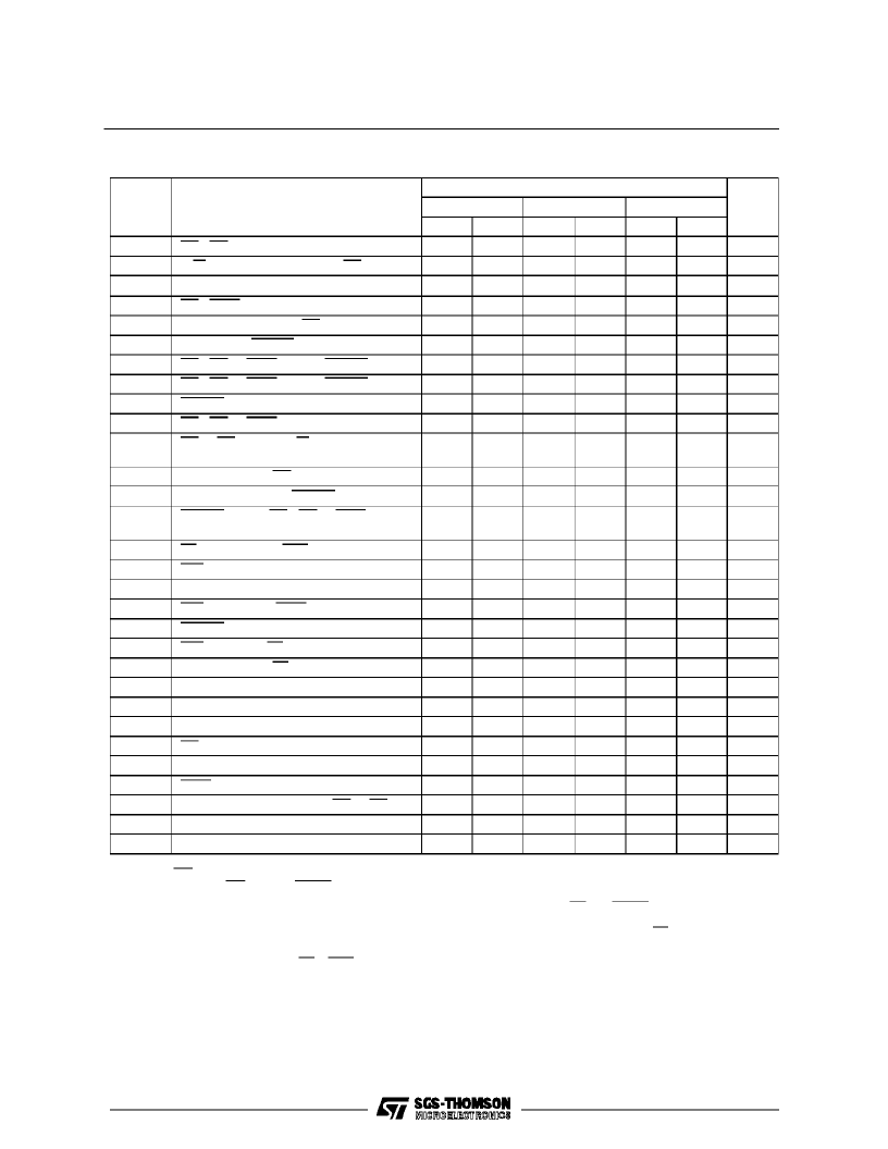
AC ELECTRICAL CHARACTERISTICS
(VCC= 5.0Vdc
±
5%, GND = 0Vdc, TA= 0
°
C to 70
°
C)
Number
Characteristic
Value
5MHz
Unit
4MHz
8MHz
Min.
50
30
280
50
100
Max.
Min.
35
25
150
50
80
Max.
Min.
25
20
100
50
50
Max.
1
2
3
CS, DS Width High
R/W, A1-A5 Valid to Falling CS (setup)
Data Valid Prior to Falling CLK
CS, IACK Valid to Falling Clock (setup)
Falling Clock to Next CS Low
CLK Low to DTACK Low
CS, DS or IACK High to DTACK High
CS, DS or IACK High to DTACK Tri-state
DTACK Low to Data Invalid (hold time)
CS, DS or IACK High to Data Tri-state
CS or DS High to R/W, A1-A5 Invalid
(hold time)
Data Valid from CS Low
Read Data Valid to DTACK Low (setup)
DTACK Low to DS, CS or IACK High
(hold time)
IEI Low to Falling CLK (setup)
IEO Valid from Clock Low (delay)
Data Valid from Clock Low (delay)
IEO Invalid from IACKHigh (delay)
DTACK Low from Clock High (delay)
IEO Valid from IEI Low (delay)
Data Valid from IEI Low (delay)
Clock Cycle Time
Clock Width Low
Clock Width High
DS Inactive to rising Clock (setup)
I/O Minimum Active Pulse Width
IACK Width High
I/O Data Valid from Rising CS or DS
Receiver Ready Delay from Rising RC
Transmitter Ready Delay from Rising TC
ns
ns
ns
ns
ns
ns
ns
ns
ns
ns
ns
4
(3)
4a
(4)
5
6
7
8
9
10
220
60
100
180
55
100
90
50
100
0
0
0
50
50
50
0
0
0
11
(3,5)
12
13
310
260
200
ns
ns
ns
50
0
50
0
20
0
14
15
(1)
16
17
18
19
(1)
20
21
22
23
24
(4)
25
26
27
28
29
50
50
50
ns
ns
ns
ns
ns
ns
ns
ns
ns
ns
ns
ns
180
300
150
180
100
220
1000
180
300
150
165
100
220
1000
120
180
100
100
100
195
1000
250
110
110
100
100
2
200
90
90
80
100
2
125
55
55
50
100
2
T
CLK
ns
ns
ns
450
600
600
450
600
600
350
200
200
Notes :
1. IEO only goes low if no acknowledgeable interrupt is
pending. If IEO goes low, DTACKand thedata bus re-
main tri-stated.
2. T
CLK
refers to theclock applied to theMFP CLK input
pin. t
CLK
refers to the timer clock signal,regardless of
whetherthatsignalcomesfromtheXTAL1/XTAL2 crys-
tal clock inputs or theTAI or TBI timerinputs.
3. If thesetup timeisnotmet,CS or IACKwillnotbereco-
gnized until thenext fallingCLK.
4.If thissetup time ismet(for consecutive cycles), the mi-
nimumhold-off time ofone clock cycle willbe obtained.
If notmet, the hold-off willbe twoclock cycles.
5.Although CS and DTACK are synchronized with the
clock, the data outduring a readcycleis asynchronous
tothe clock, relying onlyon CS for timing.
6.Spec.30 applies to timeroutputs TAO and TBO only.
TS68HC901
30/42
相關PDF資料 |
PDF描述 |
|---|---|
| TS68HC901CFN5 | HCMOS MULTI-FUNCTION PERIPHERAL |
| TS68HC901CFN8 | HCMOS MULTI-FUNCTION PERIPHERAL |
| TS68HC901CP4 | HCMOS MULTI-FUNCTION PERIPHERAL |
| TS68HC901CP5 | HCMOS MULTI-FUNCTION PERIPHERAL |
| TS68HC901CP8 | HCMOS MULTI-FUNCTION PERIPHERAL |
相關代理商/技術參數(shù) |
參數(shù)描述 |
|---|---|
| TS68HC901CFN5 | 制造商:STMICROELECTRONICS 制造商全稱:STMicroelectronics 功能描述:HCMOS MULTI-FUNCTION PERIPHERAL |
| TS68HC901CFN8 | 制造商:STMICROELECTRONICS 制造商全稱:STMicroelectronics 功能描述:HCMOS MULTI-FUNCTION PERIPHERAL |
| TS68HC901CP4 | 制造商:STMICROELECTRONICS 制造商全稱:STMicroelectronics 功能描述:HCMOS MULTI-FUNCTION PERIPHERAL |
| TS68HC901CP5 | 制造商:STMICROELECTRONICS 制造商全稱:STMicroelectronics 功能描述:HCMOS MULTI-FUNCTION PERIPHERAL |
| TS68HC901CP8 | 制造商:STMICROELECTRONICS 制造商全稱:STMicroelectronics 功能描述:HCMOS MULTI-FUNCTION PERIPHERAL |
發(fā)布緊急采購,3分鐘左右您將得到回復。