- 您現在的位置:買賣IC網 > PDF目錄382681 > TPS7148YD (Texas Instruments, Inc.) LOW-DROPOUT VOLTAGE REGULATORS PDF資料下載
參數資料
| 型號: | TPS7148YD |
| 廠商: | Texas Instruments, Inc. |
| 元件分類: | 基準電壓源/電流源 |
| 英文描述: | LOW-DROPOUT VOLTAGE REGULATORS |
| 中文描述: | 低壓差電壓調節(jié)器 |
| 文件頁數: | 5/33頁 |
| 文件大?。?/td> | 541K |
| 代理商: | TPS7148YD |
第1頁第2頁第3頁第4頁當前第5頁第6頁第7頁第8頁第9頁第10頁第11頁第12頁第13頁第14頁第15頁第16頁第17頁第18頁第19頁第20頁第21頁第22頁第23頁第24頁第25頁第26頁第27頁第28頁第29頁第30頁第31頁第32頁第33頁

TPS7101Q, TPS7133Q, TPS7148Q, TPS7150Q
TPS7101Y, TPS7133Y, TPS7148Y, TPS7150Y
LOW-DROPOUT VOLTAGE REGULATORS
SLVS092F – NOVEMBER 1994 – REVISED JANUARY 1997
5
POST OFFICE BOX 655303
DALLAS, TEXAS 75265
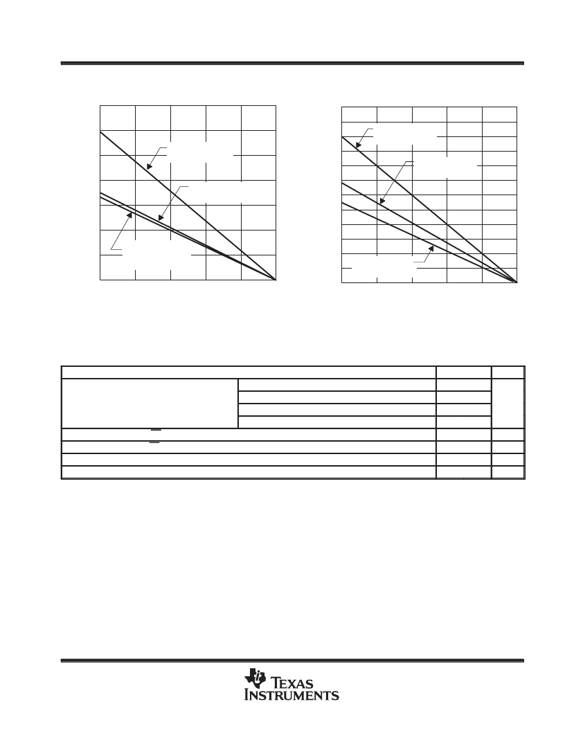
Figure 3
1200
800
400
0
25
50
75
100
–
PD
DISSIPATION DERATING CURVE
vs
FREE-AIR TEMPERATURE
125
150
1400
1000
600
200
PW and PWP
Package
R
θ
JA = 178
°
C/W
TA – Free-Air Temperature –
°
C
P Package
R
θ
JA = 106
°
C/W
D Package
R
θ
JA = 172
°
C/W
Figure 4
2400
1600
800
0
25
50
75
100
–
PD
3200
4000
DISSIPATION DERATING CURVE
vs
CASE TEMPERATURE
4800
125
150
4400
3600
2800
2000
1200
400
PW Package
R
θ
JC = 31
°
C/W
TC – Case Temperature –
°
C
D Package
R
θ
JC = 57
°
C/W
P Package
R
θ
JC = 46
°
C/W
Dissipation rating tables and figures are provided for maintenance of junction temperature at or below absolute maximum temperature of 150
°
C.
For guidelines on maintaining junction temperature within recommended operating range, see the Thermal Information section.
recommended operating conditions
MIN
2.5
MAX
UNIT
TPS7101Q
10
Input voltage VI
TPS7133Q
3.77
10
V
Input voltage, VI
TPS7148Q
5.2
10
TPS7150Q
5.33
10
High-level input voltage at EN, VIH
Low-level input voltage at EN, VIL
Output current range, IO
Operating virtual junction temperature range, TJ
Minimum input voltage defined in the recommended operating conditions is the maximum specified output voltage plus dropout voltage at the
maximum specified load range. Since dropout voltage is a function of output current, the usable range can be extended for lighter loads. To
calculate the minimum input voltage for your maximum output current, use the following equation: VI(min) = VO(max) + VDO(max load)
Because the TPS7101 s programmable, rDS(on) should be used to calculate VDO before applying the above equation. The equation for calculating
VDO from rDS(on) is given in Note 2 in the electrical characteristics table. The minimum value of 2.5 V is the absolute lower limit for the
recommended input voltage range for the TPS7101.
2
V
0.5
V
0
500
mA
°
C
–40
125
相關PDF資料 |
PDF描述 |
|---|---|
| TPS7150YD | LOW-DROPOUT VOLTAGE REGULATORS |
| TPS7150YP | LOW-DROPOUT VOLTAGE REGULATORS |
| TPS7101Q | LOW-DROPOUT VOLTAGE REGULATORS |
| TPS7101YD | LOW-DROPOUT VOLTAGE REGULATORS |
| TPS7101YP | LOW-DROPOUT VOLTAGE REGULATORS |
相關代理商/技術參數 |
參數描述 |
|---|---|
| TPS7148YP | 制造商:TI 制造商全稱:Texas Instruments 功能描述:LOW-DROPOUT VOLTAGE REGULATORS |
| TPS7148YPW | 制造商:TI 制造商全稱:Texas Instruments 功能描述:LOW-DROPOUT VOLTAGE REGULATORS |
| TPS715 | 制造商:TI 制造商全稱:Texas Instruments 功能描述:50 mA, 24 V, 3.2 uA Supply Current Low-Dropout Linear Regulator |
| TPS7150 | 制造商:未知廠家 制造商全稱:未知廠家 功能描述:Low-Dropo |
| TPS71501 | 制造商:TI 制造商全稱:Texas Instruments 功能描述:50 mA, 24 V, 3.2U Supply Current Low-Dropout Linear Regulator in SC70 Package |
發(fā)布緊急采購,3分鐘左右您將得到回復。