- 您現(xiàn)在的位置:買賣IC網(wǎng) > PDF目錄382680 > TPS7148QPW (Texas Instruments, Inc.) LOW-DROPOUT VOLTAGE REGULATORS PDF資料下載
參數(shù)資料
| 型號: | TPS7148QPW |
| 廠商: | Texas Instruments, Inc. |
| 元件分類: | 基準(zhǔn)電壓源/電流源 |
| 英文描述: | LOW-DROPOUT VOLTAGE REGULATORS |
| 中文描述: | 低壓差電壓調(diào)節(jié)器 |
| 文件頁數(shù): | 11/33頁 |
| 文件大小: | 541K |
| 代理商: | TPS7148QPW |
第1頁第2頁第3頁第4頁第5頁第6頁第7頁第8頁第9頁第10頁當(dāng)前第11頁第12頁第13頁第14頁第15頁第16頁第17頁第18頁第19頁第20頁第21頁第22頁第23頁第24頁第25頁第26頁第27頁第28頁第29頁第30頁第31頁第32頁第33頁

TPS7101Q, TPS7133Q, TPS7148Q, TPS7150Q
TPS7101Y, TPS7133Y, TPS7148Y, TPS7150Y
LOW-DROPOUT VOLTAGE REGULATORS
SLVS092F – NOVEMBER 1994 – REVISED JANUARY 1997
11
POST OFFICE BOX 655303
DALLAS, TEXAS 75265
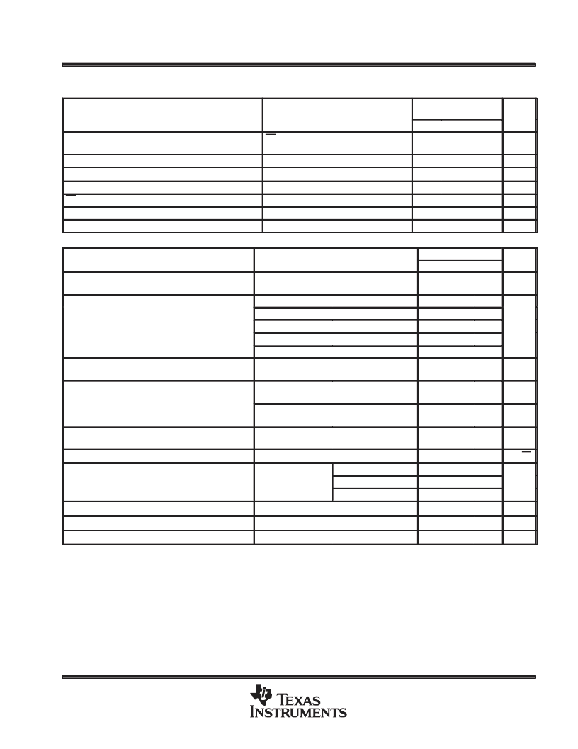
electrical characteristics at I
O
= 10 mA, EN = 0 V, C
O
= 4.7
μ
F/CSR
= 1
, T
J
= 25
°
C, SENSE/FB
shorted to OUT (unless otherwise noted)
PARAMETER
TEST CONDITIONS
TPS7101Y, TPS7133Y
TPS7148Y, TPS7150Y
MIN
TYP
UNIT
MAX
Ground current (active mode)
EN
≤
0.5 V,
0 mA
≤
IO
≤
500 mA
VO = 0,
Normal operation,
VI = VO + 1 V,
285
μ
A
Output current limit
VI = 10 V
VPG = 10 V
1.2
A
PG leakage current
0.02
μ
A
°
C
mV
Thermal shutdown junction temperature
165
EN hysteresis voltage
50
Minimum VI for active pass element
Minimum VI for valid PG
2.05
V
IPG = 300
μ
A
1.06
V
PARAMETER
TEST CONDITIONS
TPS7101Y
MIN
UNIT
TYP
MAX
Reference voltage (measured at FB with OUT
connected to FB)
VI = 3.5 V,
IO = 10 mA
1.178
V
VI = 2.4 V,
VI = 2.4 V,
VI = 2.9 V,
VI = 3.9 V,
VI = 5.9 V,
VI = 2.5 V to 10 V,
See Note 1
50
μ
A
≤
IO
≤
150 mA
150 mA
≤
IO
≤
500 mA
50
μ
A
≤
IO
≤
500 mA
50
μ
A
≤
IO
≤
500 mA
50
μ
A
≤
IO
≤
500 mA
50
μ
A
≤
IO
≤
500 mA,
0.7
0.83
Pass-element series resistance (see Note 2)
0.52
0.32
0.23
Input regulation
18
mV
Output regulation
2.5 V
≤
VI
≤
10 V,
See Note 1
IO = 5 mA to 500 mA,
14
mV
2.5 V
≤
VI
≤
10 V,
See Note 1
IO = 50
μ
A to 500 mA,
22
mV
Ripple rejection
VI = 3.5 V,
IO = 50
μ
A
VI = 3.5 V,
f = 120 Hz,
59
dB
Output noise-spectral density
f = 120 Hz
2
μ
V/
√
Hz
VI= 3.5 V,
VI = 3.5 V,
10 Hz
≤
f
≤
100 kHz,
CSR = 1
CO = 4.7
μ
F
CO = 10
μ
F
CO = 100
μ
F
Measured at VFB
IPG = 400
μ
A
VI = 3.5 V
95
Output noise voltage
89
μ
Vrms
74
PG hysteresis voltage§
VI = 3.5 V,
VI = 2.13 V,
VI = 3.5 V
12
mV
PG output low voltage§
0.1
V
FB input current
CSR refers to the total series resistance, including the ESR of the capacitor, any series resistance added externally, and PWB trace resistance
to CO.
Pulse-testing techniques are used to maintain virtual junction temperature as close as possible to ambient temperature; thermal effects must
be taken into account separately.
§Output voltage programmed to 2.5 V with closed-loop configuration (see application information).
NOTES:
1. When VI < 2.9 V and IO > 150 mA simultaneously, pass element rDS(on) increases (see Figure 27) to a point such that the resulting
dropout voltage prevents the regulator from maintaining the specified tolerance range.
2. To calculate dropout voltage, use equation:
VDO = IO
rDS(on)
rDS(on) is a function of both output current and input voltage. The parametric table lists rDS(on) for VI = 2.4 V, 2.9 V, 3.9 V, and
5.9 V, which corresponds to dropout conditions for programmed output voltages of 2.5 V, 3 V, 4 V, and 6 V, respectively. For other
programmed values, refer to Figure 26.
0.1
nA
相關(guān)PDF資料 |
PDF描述 |
|---|---|
| TPS7101Y | LOW-DROPOUT VOLTAGE REGULATORS |
| TPS7133Q | LOW-DROPOUT VOLTAGE REGULATORS |
| TPS7133Y | LOW-DROPOUT VOLTAGE REGULATORS |
| TPS7148Q | LOW-DROPOUT VOLTAGE REGULATORS |
| TPS7148QPWR | LOW-DROPOUT VOLTAGE REGULATORS |
相關(guān)代理商/技術(shù)參數(shù) |
參數(shù)描述 |
|---|---|
| TPS7148QPWLE | 制造商:TI 制造商全稱:Texas Instruments 功能描述:LOW-DROPOUT VOLTAGE REGULATORS |
| TPS7148QPWR | 功能描述:低壓差穩(wěn)壓器 - LDO Lowest Dropout PMOS RoHS:否 制造商:Texas Instruments 最大輸入電壓:36 V 輸出電壓:1.4 V to 20.5 V 回動電壓(最大值):307 mV 輸出電流:1 A 負(fù)載調(diào)節(jié):0.3 % 輸出端數(shù)量: 輸出類型:Fixed 最大工作溫度:+ 125 C 安裝風(fēng)格:SMD/SMT 封裝 / 箱體:VQFN-20 |
| TPS7148QPWRG4 | 功能描述:低壓差穩(wěn)壓器 - LDO Lowest Dropout PMOS RoHS:否 制造商:Texas Instruments 最大輸入電壓:36 V 輸出電壓:1.4 V to 20.5 V 回動電壓(最大值):307 mV 輸出電流:1 A 負(fù)載調(diào)節(jié):0.3 % 輸出端數(shù)量: 輸出類型:Fixed 最大工作溫度:+ 125 C 安裝風(fēng)格:SMD/SMT 封裝 / 箱體:VQFN-20 |
| TPS7148Y | 制造商:TI 制造商全稱:Texas Instruments 功能描述:LOW-DROPOUT VOLTAGE REGULATORS |
| TPS7148YD | 制造商:TI 制造商全稱:Texas Instruments 功能描述:LOW-DROPOUT VOLTAGE REGULATORS |
發(fā)布緊急采購,3分鐘左右您將得到回復(fù)。