- 您現(xiàn)在的位置:買賣IC網(wǎng) > PDF目錄98283 > TPS54418RTER (TEXAS INSTRUMENTS INC) 6.4 A SWITCHING REGULATOR, 2000 kHz SWITCHING FREQ-MAX, PQCC16 PDF資料下載
參數(shù)資料
| 型號: | TPS54418RTER |
| 廠商: | TEXAS INSTRUMENTS INC |
| 元件分類: | 穩(wěn)壓器 |
| 英文描述: | 6.4 A SWITCHING REGULATOR, 2000 kHz SWITCHING FREQ-MAX, PQCC16 |
| 封裝: | 3 X 3 MM, GREEN, PLASTIC, WQFN-16 |
| 文件頁數(shù): | 11/35頁 |
| 文件大小: | 1356K |
| 代理商: | TPS54418RTER |
第1頁第2頁第3頁第4頁第5頁第6頁第7頁第8頁第9頁第10頁當前第11頁第12頁第13頁第14頁第15頁第16頁第17頁第18頁第19頁第20頁第21頁第22頁第23頁第24頁第25頁第26頁第27頁第28頁第29頁第30頁第31頁第32頁第33頁第34頁第35頁
www.ti.com
SLVS946A – MAY 2009 – REVISED MAY 2010
APPLICATION INFORMATION
DESIGN GUIDE – STEP-BY-STEP DESIGN PROCEDURE
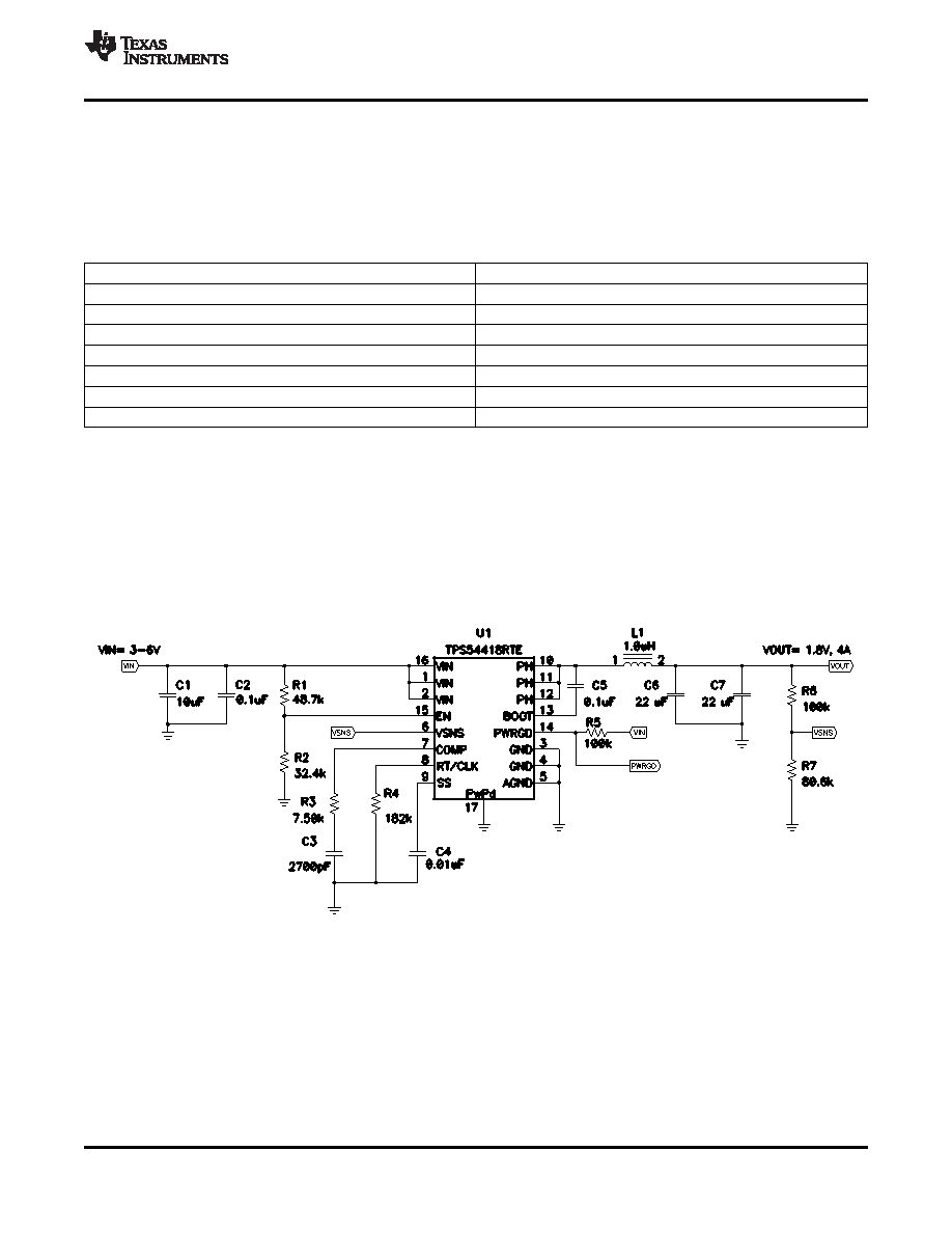
This example details the design of a high frequency switching regulator design using ceramic output capacitors.
This design is available as the HPA375 evaluation module (EVM). A few parameters must be known in order to
start the design process. These parameters are typically determined on the system level. For this example, we
start with the following known parameters:
Output Voltage
1.8 V
Transient Response 1 to 2A load step
ΔVout = 3%
Maximum Output Current
4 A
Input Voltage
3.3 V nom. 3 V to 5 V
Output Voltage Ripple
< 30 mV p-p
Start Input Voltage (rising VIN)
3.1 V
Stop Input Voltage (falling VIN)
2.8 V
Switching Frequency (Fsw)
1000 kHz
SELECTING THE SWITCHING FREQUENCY
The first step is to decide on a switching frequency for the regulator. Typically, you want to choose the highest
switching frequency possible since this produces the smallest solution size. The high switching frequency allows
for lower valued inductors and smaller output capacitors compared to a power supply that switches at a lower
frequency. However, the highest switching frequency causes extra switching losses, which hurt the converter’s
performance. The converter is capable of running from 200 kHz to 2 MHz. Unless a small solution size is an
ultimate goal, a moderate switching frequency of 1MHz is selected to achieve both a small solution size and a
high efficiency operation. Using Equation 5, R4 is calculated to be 180 k
. A standard 1% 182 k value was
chosen in the design.
Figure 33. High Frequency, 1.8 V Output Power Supply Design with Adjusted UVLO
OUTPUT INDUCTOR SELECTION
The inductor selected works for the entire TPS54418 input voltage range. To calculate the value of the output
inductor, use Equation 18. KIND is a coefficient that represents the amount of inductor ripple current relative to the
maximum output current. The inductor ripple current is filtered by the output capacitor. Therefore, choosing high
inductor ripple currents impacts the selection of the output capacitor since the output capacitor must have a
ripple current rating equal to or greater than the inductor ripple current. In general, the inductor ripple value is at
the discretion of the designer; however, KIND is normally from 0.1 to 0.3 for the majority of applications.
Copyright 2009–2010, Texas Instruments Incorporated
19
Product Folder Link(s): TPS54418
相關PDF資料 |
PDF描述 |
|---|---|
| TPS54426PWP | 7.5 A SWITCHING REGULATOR, 700 kHz SWITCHING FREQ-MAX, PDSO14 |
| TPS54429PWP | 0.01 A SWITCHING REGULATOR, 700 kHz SWITCHING FREQ-MAX, PDSO14 |
| TPS5450MDDAREP | 11.7 A SWITCHING REGULATOR, 600 kHz SWITCHING FREQ-MAX, PDSO8 |
| TPS54519RTER | 8 A SWITCHING REGULATOR, 2000 kHz SWITCHING FREQ-MAX, PQCC16 |
| TPS54612MPWPREP | 12 A SWITCHING REGULATOR, 700 kHz SWITCHING FREQ-MAX, PDSO28 |
相關代理商/技術參數(shù) |
參數(shù)描述 |
|---|---|
| TPS54418RTERG4 | 制造商:Texas Instruments 功能描述: |
| TPS54418RTET | 功能描述:直流/直流開關調節(jié)器 2.95-6Vin 4A 2MHz Synch St Down RoHS:否 制造商:International Rectifier 最大輸入電壓:21 V 開關頻率:1.5 MHz 輸出電壓:0.5 V to 0.86 V 輸出電流:4 A 輸出端數(shù)量: 最大工作溫度: 安裝風格:SMD/SMT 封裝 / 箱體:PQFN 4 x 5 |
| TPS54424RNVT | 功能描述:4.5V TO 17V INPUT, CURRENT MODE, 制造商:texas instruments 系列:SWIFT?? 包裝:剪切帶(CT) 零件狀態(tài):在售 功能:降壓 輸出配置:正 拓撲:降壓 輸出類型:可調式 輸出數(shù):1 電壓 - 輸入(最小值):4.5V 電壓 - 輸入(最大值):17V 電壓 - 輸出(最小值/固定):0.6V 電壓 - 輸出(最大值):12V 電流 - 輸出:4A 頻率 - 開關:200kHz ~ 1.6MHz 同步整流器:是 工作溫度:-40°C ~ 150°C(TJ) 安裝類型:表面貼裝 封裝/外殼:18-VFQFN 供應商器件封裝:18-VQFN-HR(3.5x3.5) 標準包裝:1 |
| TPS54425 | 制造商:TI 制造商全稱:Texas Instruments 功能描述:4-A OUTPUT SINGLE SYNCHRONOUS STEP DOWN SWITCHER WITH INTEGRATED FET ( SWIFT?) |
| TPS54425_10 | 制造商:TI 制造商全稱:Texas Instruments 功能描述:4-A OUTPUT SINGLE SYNCHRONOUS STEP DOWN SWITCHER WITH INTEGRATED FET ( SWIFT?) |
發(fā)布緊急采購,3分鐘左右您將得到回復。