- 您現(xiàn)在的位置:買賣IC網(wǎng) > PDF目錄385945 > TPS2022P (Texas Instruments, Inc.) POWER-DISTRIBUTION SWITCHES PDF資料下載
參數(shù)資料
| 型號(hào): | TPS2022P |
| 廠商: | Texas Instruments, Inc. |
| 英文描述: | POWER-DISTRIBUTION SWITCHES |
| 中文描述: | 配電開關(guān) |
| 文件頁數(shù): | 18/23頁 |
| 文件大?。?/td> | 377K |
| 代理商: | TPS2022P |
TPS2020, TPS2021, TPS2022, TPS2023, TPS2024
POWER-DISTRIBUTION SWITCHES
SLVS175A – DECEMBER 1998 – REVISED NOVEMBER 1999
18
POST OFFICE BOX 655303
DALLAS, TEXAS 75265
APPLICATION INFORMATION
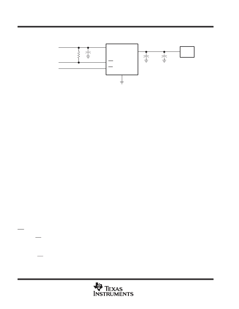
IN
OC
EN
GND
1
0.1
μ
F
2,3
5
4
6,7,8
0.1
μ
F
22
μ
F
Load
OUT
TPS2024
Power Supply
2.7 V to 5.5 V
10 k
Figure 38. Typical Application
power-supply considerations
A 0.01-
μ
F to 0.1-
μ
F ceramic bypass capacitor between IN and GND, close to the device, is recommended.
Placing a high-value electrolytic capacitor on the output and input pins is recommended when the output load
is heavy. This precaution reduces power supply transients that may cause ringing on the input. Additionally,
bypassing the output with a 0.01-
μ
F to 0.1-
μ
F ceramic capacitor improves the immunity of the device to
short-circuit transients.
overcurrent
A sense FET checks for overcurrent conditions. Unlike current-sense resistors, sense FETs do not increase the
series resistance of the current path. When an overcurrent condition is detected, the device maintains a
constant output current and reduces the output voltage accordingly. Complete shutdown occurs only if the fault
is present long enough to activate thermal limiting.
Three possible overload conditions can occur. In the first condition, the output has been shorted before the
device is enabled or before V
I(IN)
has been applied (see Figure 6). The TPS202x senses the short and
immediately switches into a constant-current output.
In the second condition, the excessive load occurs while the device is enabled. At the instant the excessive load
occurs, very high currents may flow for a short time before the current-limit circuit can react (see Figures 13–22).
After the current-limit circuit has tripped (reached the overcurrent trip threshhold) the device switches into
constant-current mode.
In the third condition, the load has been gradually increased beyond the recommended operating current. The
current is permitted to rise until the current-limit threshold is reached or until the thermal limit of the device is
exceeded (see Figures 7–11). The TPS202x is capable of delivering current up to the current-limit threshold
without damaging the device. Once the threshold has been reached, the device switches into its
constant-current mode.
OC response
The OC open-drain output is asserted (active low) when an overcurrent or overtemperature condition is
encountered. The output will remain asserted until the overcurrent or overtemperature condition is removed.
Connecting a heavy capacitive load to an enabled device can cause momentary false overcurrent reporting from
the inrush current flowing through the device, charging the downstream capacitor. An RC filter can be connected
to the OC pin to reduce false overcurrent reporting. Using low-ESR electrolytic capacitors on the output lowers
the inrush current flow through the device during hot-plug events by providing a low impedance energy source,
thereby reducing erroneous overcurrent reporting.
相關(guān)PDF資料 |
PDF描述 |
|---|---|
| TPS202X | USB POWER DISTRIBUTION |
| TPS204X | USB POWER DISTRIBUTION |
| TPS203X | USB POWER DISTRIBUTION |
| TPS2032P | POWER-DISTRIBUTION SWITCHES |
| TPS2033P | POWER-DISTRIBUTION SWITCHES |
相關(guān)代理商/技術(shù)參數(shù) |
參數(shù)描述 |
|---|---|
| TPS2022PE4 | 功能描述:電源開關(guān) IC - USB 1.1A 2.7-5.5V Sngl Hi-Side MOSFET RoHS:否 制造商:Micrel 電源電壓-最小:2.7 V 電源電壓-最大:5.5 V 最大工作溫度:+ 85 C 最小工作溫度:- 40 C 封裝 / 箱體:SOIC-8 封裝:Tube |
| TPS2022-Q1 | 制造商:TI 制造商全稱:Texas Instruments 功能描述:POWER-DISTRIBUTION SWITCHES |
| TPS2023 | 制造商:TI 制造商全稱:Texas Instruments 功能描述:POWER-DISTRIBUTION SWITCHES |
| TPS2023D | 功能描述:電源開關(guān) IC - USB 1.65A 2.7-5.5V Sngl Hi-Side MOSFET RoHS:否 制造商:Micrel 電源電壓-最小:2.7 V 電源電壓-最大:5.5 V 最大工作溫度:+ 85 C 最小工作溫度:- 40 C 封裝 / 箱體:SOIC-8 封裝:Tube |
| TPS2023D | 制造商:Texas Instruments 功能描述:IC 2.2A POWER DIST SWITCH 8-SOIC 制造商:Texas Instruments 功能描述:IC, 2.2A POWER DIST SWITCH 8-SOIC 制造商:Texas Instruments 功能描述:IC, 2.2A POWER DIST SWITCH 8-SOIC; Primary Input Voltage:5.5V; No. of Outputs:1; Output Current:1.5A; Voltage Regulator Case Style:SOIC; No. of Pins:8; Operating Temperature Min:-40C; Operating Temperature Max:85C; SVHC:No SVHC ;RoHS Compliant: Yes |
發(fā)布緊急采購,3分鐘左右您將得到回復(fù)。