- 您現(xiàn)在的位置:買賣IC網(wǎng) > PDF目錄68418 > TPS2011DRG4 (TEXAS INSTRUMENTS INC) 1-CHANNEL POWER SUPPLY SUPPORT CKT, PDSO8 PDF資料下載
參數(shù)資料
| 型號: | TPS2011DRG4 |
| 廠商: | TEXAS INSTRUMENTS INC |
| 元件分類: | 電源管理 |
| 英文描述: | 1-CHANNEL POWER SUPPLY SUPPORT CKT, PDSO8 |
| 封裝: | GREEN, SOIC-8 |
| 文件頁數(shù): | 17/21頁 |
| 文件大?。?/td> | 553K |
| 代理商: | TPS2011DRG4 |
TPS2010, TPS2011, TPS2012, TPS2013
POWER-DISTRIBUTION
SLVS097A – DECEMBER 1994 – REVISED AUGUST 1995
5
POST OFFICE BOX 655303
DALLAS, TEXAS 75265
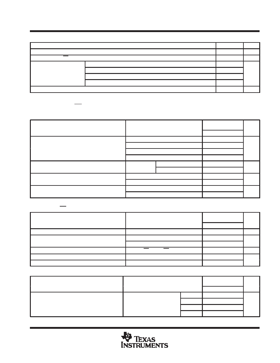
recommended operating conditions
MIN
MAX
UNIT
Input voltage, VI(IN)
2.7
5.5
V
Input voltage, VI at EN
0
5.5
V
TPS2010
0
0.2
Continuous output current IO
TPS2011
0
0.6
A
Continuous output current, IO
TPS2012
0
1
A
TPS2013
0
1.5
Operating virtual junction temperature, TJ
–40
125
°C
electrical characteristics over recommended operating junction temperature range, VI(IN) = 5.5 V,
IO = rated current, EN = 0 V (unless otherwise noted)
power switch
PARAMETER
TEST CONDITIONS
TPS2010, TPS2011
TPS2012, TPS2013
UNIT
PARAMETER
TEST CONDITIONS
MIN
TYP
MAX
UNIT
VI(IN) = 5.5 V,
TJ = 25°C
75
95
On state resistance
VI(IN) = 4.5 V,
TJ = 25°C
80
110
m
On-state resistance
VI(IN) = 3 V,
TJ = 25°C
120
175
m
VI(IN) = 2.7 V,
TJ = 25°C
140
215
Output leakage current
EN
VI(IN)
TJ = 25°C
0.001
1
A
Output leakage current
EN = VI(IN)
–40
°C ≤ TJ ≤ 125°C
10
A
t
Output rise time
VI(IN) = 5.5 V,
TJ = 25°C,
CL = 1 F
4
ms
tr
Output rise time
VI(IN) = 2.7 V,
TJ = 25°C,
CL = 1 F
3.8
ms
tf
Output fall time
VI(IN) = 5.5 V,
TJ = 25°C,
CL = 1 F
3.9
ms
tf
Output fall time
VI(IN) = 2.7 V,
TJ = 25°C,
CL = 1 F
3.5
ms
Pulse-testing techniques maintain junction temperature close to ambient temperature; thermal effects must be taken into account separately.
enable input (EN)
PARAMETER
TEST CONDITIONS
TPS2010, TPS2011
TPS2012, TPS2013
UNIT
PARAMETER
TEST CONDITIONS
MIN
TYP
MAX
UNIT
High-level input voltage
2.7 V
≤ VI(IN) ≤ 5.5 V
2
V
Low level input voltage
4.5 V
≤ VI(IN) ≤ 5.5 V
0.8
V
Low-level input voltage
2.7 V
≤ VI(IN) < 4.5 V
0.4
V
Input current
EN = 0 V or EN = VI(IN)
– 0.5
0.5
A
tPLH Propagation (delay) time, low-to-high-level output
CL = 1 F
20
ms
tPHL Propagation (delay) time, high-to-low-level output
CL = 1 F
40
ms
current limit
PARAMETER
TEST CONDITIONS
TPS2010, TPS2011
TPS2012, TPS2013
UNIT
TEST CONDITIONS
MIN
TYP
MAX
TJ =25°C
TPS2010
0.22
0.4
0.6
Short circuit current
TJ = 25 C,
VI(IN) = 5.5 V,
TPS2011
0.66
1.2
1.8
A
Short-circuit current
I(IN)
OUT connected to GND, device
enabled into short circuit
TPS2012
1.1
2
3
A
enabled into short circuit
TPS2013
1.65
2.6
4.5
Pulse-testing techniques maintain junction temperature close to ambient temperature; thermal effects must be taken into account separately.
相關(guān)PDF資料 |
PDF描述 |
|---|---|
| TPS2010DRG4 | 1-CHANNEL POWER SUPPLY SUPPORT CKT, PDSO8 |
| TPS2012DRG4 | 1-CHANNEL POWER SUPPLY SUPPORT CKT, PDSO8 |
| TPS2010PWRG4 | 1-CHANNEL POWER SUPPLY SUPPORT CKT, PDSO14 |
| TPS2013DG4 | 1-CHANNEL POWER SUPPLY SUPPORT CKT, PDSO8 |
| TPS2011D | 1-CHANNEL POWER SUPPLY SUPPORT CKT, PDSO8 |
相關(guān)代理商/技術(shù)參數(shù) |
參數(shù)描述 |
|---|---|
| TPS2011PW | 制造商:TI 制造商全稱:Texas Instruments 功能描述:POWER-DISTRIBUTION |
| TPS2011PWLE | 制造商:TI 制造商全稱:Texas Instruments 功能描述:POWER-DISTRIBUTION |
| TPS2012 | 功能描述:臺式示波器 Oscilloscope 100MHz Digital 1 GS/S, 2-Ch RoHS:否 制造商:Teledyne LeCroy 通道:4 帶寬:1 GHz 采樣比:2.5 GS/s 顯示器類型:Color TFT, LCD 輸入電壓:100 VAC to 240 VAC 設(shè)備類型:Digital Oscilloscopes 電纜類型:Global Power Cord Sets Included |
| TPS2012 FRENCH | 制造商:Tektronix Inc 功能描述:OSCILLOSCOPE 2 CHANNEL |
| TPS2012 GERMAN | 制造商:Tektronix Inc 功能描述:OSCILLOSCOPE 2 CHANNEL |
發(fā)布緊急采購,3分鐘左右您將得到回復(fù)。