- 您現在的位置:買賣IC網 > PDF目錄385945 > TPIC6596DW (Texas Instruments, Inc.) POWER LOGIC 8-BIT SHIFT REGISTER PDF資料下載
參數資料
| 型號: | TPIC6596DW |
| 廠商: | Texas Instruments, Inc. |
| 元件分類: | 通用總線功能 |
| 英文描述: | POWER LOGIC 8-BIT SHIFT REGISTER |
| 中文描述: | 功率邏輯8位移位寄存器 |
| 文件頁數: | 3/10頁 |
| 文件大小: | 155K |
| 代理商: | TPIC6596DW |
TPIC6596
POWER LOGIC 8-BIT SHIFT REGISTER
SLIS096 – APRIL 2000
3
POST OFFICE BOX 655303
DALLAS, TEXAS 75265
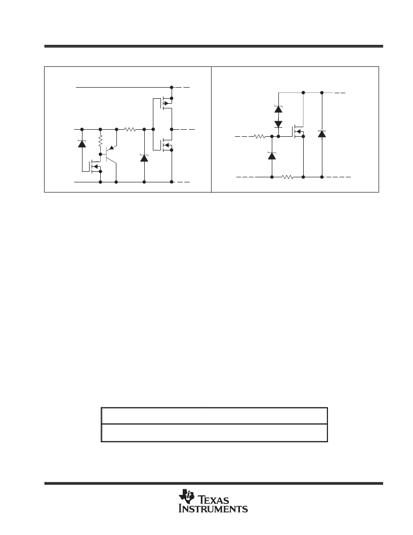
schematic of inputs and outputs
EQUIVALENT OF EACH INPUT
TYPICAL OF ALL DRAIN OUTPUTS
VCC
Input
LGND
PGND
DRAIN
45 V
12 V
25 V
12 V
LGND
absolute maximum ratings over recommended operating case temperature range (unless
otherwise noted)
Logic supply voltage, V
CC
(see Note 1)
Logic input voltage range, V
I
Power DMOS drain-to-source voltage, V
DS
(see Note 2)
Continuous source-drain diode anode current
Pulsed source-drain diode anode current
Pulsed drain current, each output, all outputs on, I
Dn,
T
A
= 25
°
C (see Note 3)
Continuous drain current, each output, all outputs on, I
Dn,
T
A
= 25
°
C
Peak drain current single output, I
DM,
T
A
= 25
°
C (see Note 3)
Single-pulse avalanche energy, E
AS
(see Figure 4)
Avalanche current, I
AS
(see Note 4)
. . . . . . . . . . . . . . . . . . . . . . . . . . . . . . . . . . . . . . . . . . . . . . . . . . . . . . . . . .
Continuous total power dissipation
. . . . . . . . . . . . . . . . . . . . . . . . . . . . . . . . . . . . .
Operating virtual junction temperature range, T
J
. . . . . . . . . . . . . . . . . . . . . . . . . . . . . . . . . . . . .
Storage temperature range, T
stg
. . . . . . . . . . . . . . . . . . . . . . . . . . . . . . . . . . . . . . . . . . . . . . . . . . .
Lead temperature 1,6 mm (1/16 inch) from case for 10 seconds
7 V
. . . . . . . . . . . . . . . . . . . . . . . . . . . . . . . . . . . . . . . . . . . . . . . . . . . . . . .
. . . . . . . . . . . . . . . . . . . . . . . . . . . . . . . . . . . . . . . . . . . . . . . . . . . . . . . .
. . . . . . . . . . . . . . . . . . . . . . . . . . . . . . . . . . . . . . . .
. . . . . . . . . . . . . . . . . . . . . . . . . . . . . . . . . . . . . . . . . . . . . . . . . .
. . . . . . . . . . . . . . . . . . . . . . . . . . . . . . . . . . . . . . . . . . . . . . . . . . . . . .
–0.3 V to 7 V
45 V
1 A
2 A
750 mA
250 mA
. . . . . . . . . . . . . . . . . . .
. . . . . . . . . . . . . . . . . . . . . . . . . .
. . . . . . . . . . . . . . . . . . . . . . . . . . . . . . . . . . . . .
. . . . . . . . . . . . . . . . . . . . . . . . . . . . . . . . . . . . . . . . . . .
2 A
75 mJ
1 A
See Dissipation Rating Table
–40
°
C to 150
°
C
–65
°
C to 150
°
C
. . . . . . . . . . . . . . . . . . . . . . . . . . . . . . .
260
°
C
Stresses beyond those listed under “absolute maximum ratings” may cause permanent damage to the device. These are stress ratings only and
functional operation of the device at these or any other conditions beyond those indicated under “recommended operating conditions” is not
implied. Exposure to absolute-maximum-rated conditions for extended periods may affect device reliability.
NOTES:
1. All voltage values are with respect to LGND and PGND.
2. Each power DMOS source is internally connected to PGND.
3. Pulse duration
≤
100
μ
s, duty cycle
≤
2 %
4. DRAIN supply voltage = 15 V, starting junction temperature (TJS) = 25
°
C, L = 100 mH, IAS = 1 A (see Figure 4).
DISSIPATION RATING TABLE
PACKAGE
TA
≤
25
°
C
POWER RATING
DERATING FACTOR
ABOVE TA = 25
°
C
9.0 mW/
°
C
9.2 mW/
°
C
TA = 125
°
C
POWER RATING
DW
1125 mW
225 mW
N
1150 mW
230 mW
相關PDF資料 |
PDF描述 |
|---|---|
| TPIC6B259(中文) | 8-Bit Addressable Latch(功率邏輯8位可尋址鎖存器) |
| TPIC6B273(中文) | Octal D-Type Latch(功率邏輯八D鎖存器) |
| TPIC6B595(中文) | 8-Bit Shift Register(功率邏輯8位移位寄存器) |
| TPR175 | NPN SILICON RF-MICROWAVE POWER TRANSISTOR |
| TPS1100(中文) | Single P-Channel Enhancment-Mode MOSFET(單路P溝道增強方式MOSFET) |
相關代理商/技術參數 |
參數描述 |
|---|---|
| TPIC6596DWG4 | 功能描述:計數器移位寄存器 8bit Shift RoHS:否 制造商:Texas Instruments 計數器類型: 計數順序:Serial to Serial/Parallel 電路數量:1 封裝 / 箱體:SOIC-20 Wide 邏輯系列: 邏輯類型: 輸入線路數量:1 輸出類型:Open Drain 傳播延遲時間:650 ns 最大工作溫度:+ 125 C 最小工作溫度:- 40 C 封裝:Reel |
| TPIC6596DWR | 功能描述:計數器移位寄存器 8 BIT SHIFT REGISTER RoHS:否 制造商:Texas Instruments 計數器類型: 計數順序:Serial to Serial/Parallel 電路數量:1 封裝 / 箱體:SOIC-20 Wide 邏輯系列: 邏輯類型: 輸入線路數量:1 輸出類型:Open Drain 傳播延遲時間:650 ns 最大工作溫度:+ 125 C 最小工作溫度:- 40 C 封裝:Reel |
| TPIC6596DWRG4 | 功能描述:計數器移位寄存器 8-BIT SHIFT REGISTER RoHS:否 制造商:Texas Instruments 計數器類型: 計數順序:Serial to Serial/Parallel 電路數量:1 封裝 / 箱體:SOIC-20 Wide 邏輯系列: 邏輯類型: 輸入線路數量:1 輸出類型:Open Drain 傳播延遲時間:650 ns 最大工作溫度:+ 125 C 最小工作溫度:- 40 C 封裝:Reel |
| TPIC6596N | 功能描述:計數器移位寄存器 8-BIT SHIFT REGISTER RoHS:否 制造商:Texas Instruments 計數器類型: 計數順序:Serial to Serial/Parallel 電路數量:1 封裝 / 箱體:SOIC-20 Wide 邏輯系列: 邏輯類型: 輸入線路數量:1 輸出類型:Open Drain 傳播延遲時間:650 ns 最大工作溫度:+ 125 C 最小工作溫度:- 40 C 封裝:Reel |
| TPIC6A259 | 制造商:TI 制造商全稱:Texas Instruments 功能描述:POWER LOGIC 8-BIT ADDRESSABLE LATCH |
發(fā)布緊急采購,3分鐘左右您將得到回復。