- 您現(xiàn)在的位置:買(mǎi)賣(mài)IC網(wǎng) > PDF目錄385934 > TLV5610EVM (Texas Instruments, Inc.) TLV5610 Evaluation Module(TLC5610評(píng)估板) PDF資料下載
參數(shù)資料
| 型號(hào): | TLV5610EVM |
| 廠商: | Texas Instruments, Inc. |
| 英文描述: | TLV5610 Evaluation Module(TLC5610評(píng)估板) |
| 中文描述: | TLV5610評(píng)估模塊(TLC5610評(píng)估板) |
| 文件頁(yè)數(shù): | 20/32頁(yè) |
| 文件大小: | 395K |
| 代理商: | TLV5610EVM |
第1頁(yè)第2頁(yè)第3頁(yè)第4頁(yè)第5頁(yè)第6頁(yè)第7頁(yè)第8頁(yè)第9頁(yè)第10頁(yè)第11頁(yè)第12頁(yè)第13頁(yè)第14頁(yè)第15頁(yè)第16頁(yè)第17頁(yè)第18頁(yè)第19頁(yè)當(dāng)前第20頁(yè)第21頁(yè)第22頁(yè)第23頁(yè)第24頁(yè)第25頁(yè)第26頁(yè)第27頁(yè)第28頁(yè)第29頁(yè)第30頁(yè)第31頁(yè)第32頁(yè)
Standalone Testing
3-2
3.1
Standalone Testing
Connect a positive DC source of 3.3 to 5 volts to the EVM at connector J1–1
referenced to J1–2. LED indicators D1 and D3 should illuminate, indicating
that power is applied to the board, and the EVM is in test mode.
3.1.1
Test Mode—Factory Defaults
Jumpers W10, W12, and W14 are open. This allows the serial data and frame
sync signals to be directed to each data converter. Frame sync is automatically
generated and occurs every sixteenth clock cycle. Trim potentiometers R3 and
R4 are set to provide U3 and U5 with 2.048V, while trim potentiometer R36
provides U4 with 4.096 V.
Switch banks SW1 through SW4 are located along the bottom edge of the
EVM. These switches are factory set to provide the digital-to-analog
converters with hex word 0x0800. This word translates to half-scale output on
channel 0 of each converter, and can be seen on pin 1 of connectors J3 (U5),
J2 (U3), and J4 (U4).
3.1.2
Test Mode—TLV5604/14
Closing jumpers W10 and W12 allows independent testing of the four-channel
data converter at U5.
Switch bank SW4 is used for channel selection, power down, and conversion
speed. Selection of channels 0 through 4 requires the setting/clearing of bits
D15 and D14. Setting bit D13 will put the data converter in power-down mode.
Setting bit D12 will choose fast conversion mode. Switch banks SW3, SW2,
and SW1 provide the digital input to the converter.
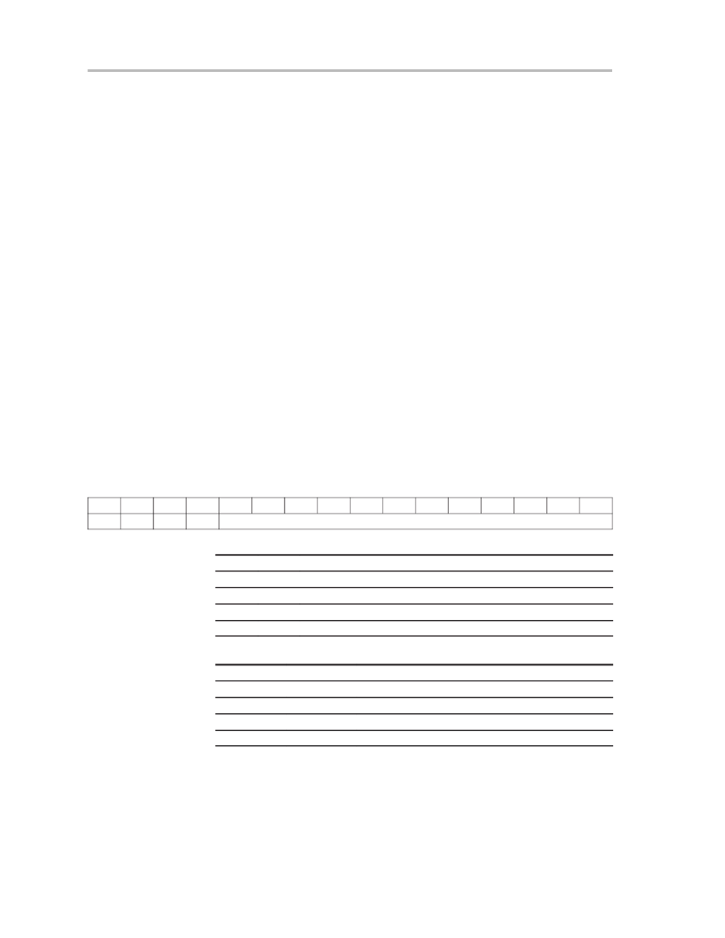
TLV5604/14 Register Configuration:
D15
D14
D13
D12
D11
D10
D9
D8
D7
D6
D5
D4
D3
D2
D1
D0
A0
A1
PWR
SPD
DAC Value
Channel Selection:
A1
A0
DAC/Output Connector
0
0
OUT A / J3–1
0
1
OUT B / J3–3
1
0
OUT C / J3–5
1
1
OUT D / J3–7
Power and Speed Selection:
D13 – PWR
D12 – SPD
Function
0
X
Normal Operation
1
X
Power Down Mode
X
0
Slow conversion mode
X
1
Fast conversion mode
DAC Output Value:
Vout = 2Vref CODE/0x1000
Data bits D11 through D0 set the digital input value to be converted. Each bit
can be set independently by sliding the appropriate switch to the on position
(towards the middle of the EVM). Data is presented to the converter MSB first.
On the 10-bit TLV5604, data in locations D1 and D0 are ignored.
相關(guān)PDF資料 |
PDF描述 |
|---|---|
| TLV5614EVM | TLV5614 Evaluation Module(TLC5614評(píng)估板) |
| TLV5630EVM | TLV5630 Evaluation Module(TLC5630評(píng)估板) |
| TLV5613(中文) | 2.7V TO 5.5V 12-Bit Parallel DAC With Power Down(具有掉電功能的2.7V至5.5V,12位并行DAC) |
| TLV5614(中文) | 2.7V to 5.5V 12-Bit 3us Quadruple Digital-to-Analog Converters With Power Down(具有掉電功能的2.7V至5.5V,12位,3微秒,四路DAC) |
| TLV5616(中文) | 2.7V TO 5.5V 12-Bit DAC With Serial Power Down(具有掉電功能的2.7V至5.5V,12位串行DAC) |
相關(guān)代理商/技術(shù)參數(shù) |
參數(shù)描述 |
|---|---|
| TLV5610IDW | 功能描述:數(shù)模轉(zhuǎn)換器- DAC 12bit 8Chl DAC RoHS:否 制造商:Texas Instruments 轉(zhuǎn)換器數(shù)量:1 DAC 輸出端數(shù)量:1 轉(zhuǎn)換速率:2 MSPs 分辨率:16 bit 接口類(lèi)型:QSPI, SPI, Serial (3-Wire, Microwire) 穩(wěn)定時(shí)間:1 us 最大工作溫度:+ 85 C 安裝風(fēng)格:SMD/SMT 封裝 / 箱體:SOIC-14 封裝:Tube |
| TLV5610IDW | 制造商:Texas Instruments 功能描述:IC's |
| TLV5610IDWG4 | 功能描述:數(shù)模轉(zhuǎn)換器- DAC 2.7V to 5.5V 12-Bit 8-Ch Ser RoHS:否 制造商:Texas Instruments 轉(zhuǎn)換器數(shù)量:1 DAC 輸出端數(shù)量:1 轉(zhuǎn)換速率:2 MSPs 分辨率:16 bit 接口類(lèi)型:QSPI, SPI, Serial (3-Wire, Microwire) 穩(wěn)定時(shí)間:1 us 最大工作溫度:+ 85 C 安裝風(fēng)格:SMD/SMT 封裝 / 箱體:SOIC-14 封裝:Tube |
| TLV5610IDWR | 功能描述:數(shù)模轉(zhuǎn)換器- DAC 2.7V to 5.5V 12-Bit 8-Ch Ser RoHS:否 制造商:Texas Instruments 轉(zhuǎn)換器數(shù)量:1 DAC 輸出端數(shù)量:1 轉(zhuǎn)換速率:2 MSPs 分辨率:16 bit 接口類(lèi)型:QSPI, SPI, Serial (3-Wire, Microwire) 穩(wěn)定時(shí)間:1 us 最大工作溫度:+ 85 C 安裝風(fēng)格:SMD/SMT 封裝 / 箱體:SOIC-14 封裝:Tube |
| TLV5610IDWRG4 | 功能描述:數(shù)模轉(zhuǎn)換器- DAC 2.7V to 5.5V 12-Bit 8-Ch Ser RoHS:否 制造商:Texas Instruments 轉(zhuǎn)換器數(shù)量:1 DAC 輸出端數(shù)量:1 轉(zhuǎn)換速率:2 MSPs 分辨率:16 bit 接口類(lèi)型:QSPI, SPI, Serial (3-Wire, Microwire) 穩(wěn)定時(shí)間:1 us 最大工作溫度:+ 85 C 安裝風(fēng)格:SMD/SMT 封裝 / 箱體:SOIC-14 封裝:Tube |
發(fā)布緊急采購(gòu),3分鐘左右您將得到回復(fù)。