- 您現(xiàn)在的位置:買賣IC網(wǎng) > PDF目錄98254 > TLV320AIC32IRHBT (TEXAS INSTRUMENTS INC) SPECIALTY CONSUMER CIRCUIT, PQCC32 PDF資料下載
參數(shù)資料
| 型號: | TLV320AIC32IRHBT |
| 廠商: | TEXAS INSTRUMENTS INC |
| 元件分類: | 消費家電 |
| 英文描述: | SPECIALTY CONSUMER CIRCUIT, PQCC32 |
| 封裝: | 5 X 5 MM, GREEN, PLASTIC, QFN-32 |
| 文件頁數(shù): | 30/80頁 |
| 文件大小: | 1270K |
| 代理商: | TLV320AIC32IRHBT |
第1頁第2頁第3頁第4頁第5頁第6頁第7頁第8頁第9頁第10頁第11頁第12頁第13頁第14頁第15頁第16頁第17頁第18頁第19頁第20頁第21頁第22頁第23頁第24頁第25頁第26頁第27頁第28頁第29頁當前第30頁第31頁第32頁第33頁第34頁第35頁第36頁第37頁第38頁第39頁第40頁第41頁第42頁第43頁第44頁第45頁第46頁第47頁第48頁第49頁第50頁第51頁第52頁第53頁第54頁第55頁第56頁第57頁第58頁第59頁第60頁第61頁第62頁第63頁第64頁第65頁第66頁第67頁第68頁第69頁第70頁第71頁第72頁第73頁第74頁第75頁第76頁第77頁第78頁第79頁第80頁

0dBto -78dB
0dBto -78dB
+
LINE2L/MIC2L
LINE2R/MIC2R
PGA_L
PGA_R
DAC_L1
DAC_R1
ANALOG HIGH POWER OUTPUT DRIVERS
SLAS479C – AUGUST 2005 – REVISED DECEMBER 2008 ............................................................................................................................................. www.ti.com
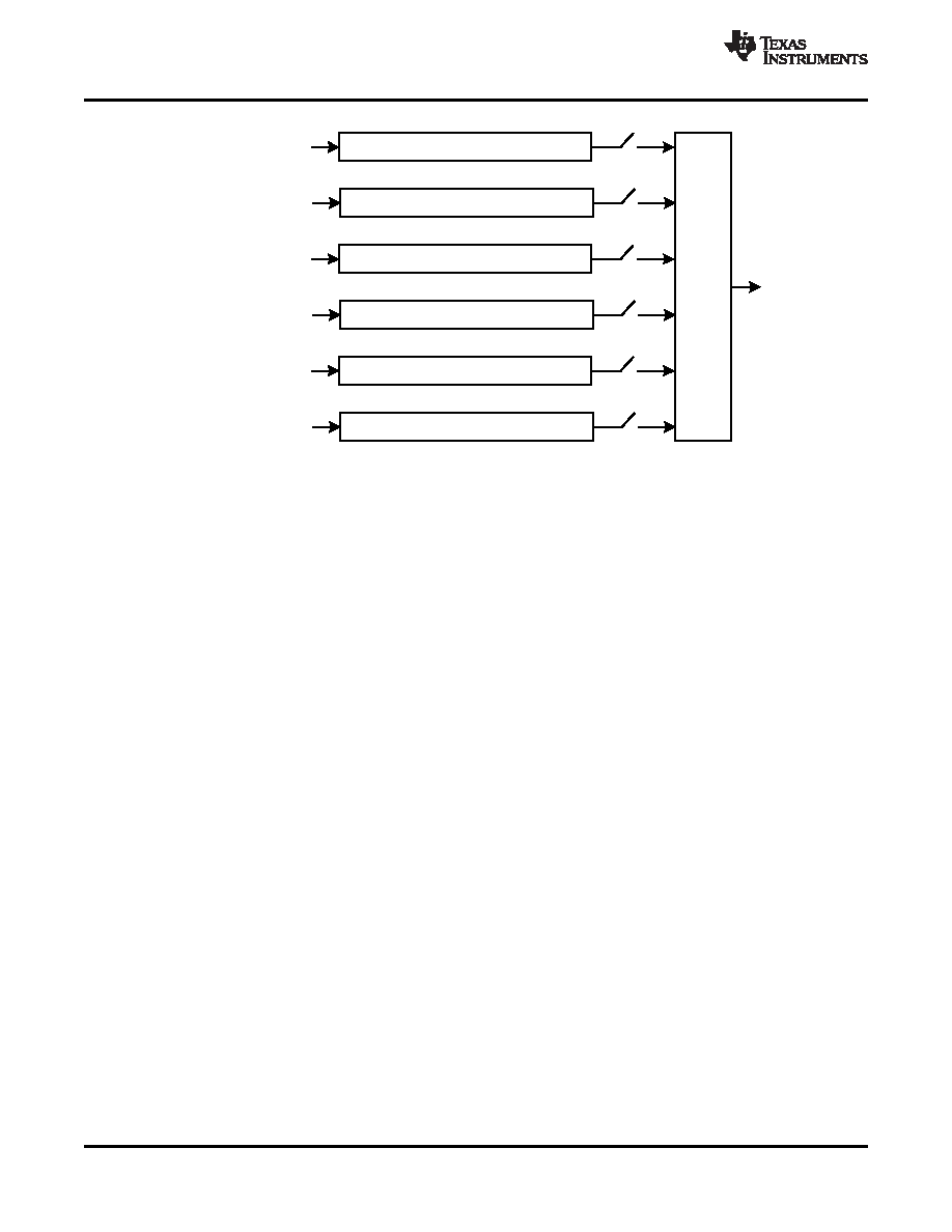
Figure 32. Detail of the Volume Control and Mixing Function Shown in Figure 25 and Figure 16
The DAC_L/R signals are the outputs of the stereo audio DAC, which can be steered by register control based
on the requirements of the system. If mixing of the DAC audio with other signals is not required, and the DAC
output is only needed at the stereo line outputs, then it is recommended to use the routing through path
DAC_L3/R3 to the fully differential stereo line outputs. This results not only in higher quality output performance,
but also in lower power operation, since the analog volume controls and mixing blocks ahead of these drivers
can be powered down. This signal path will attenuate the signal by a factor of 1 dB.
If instead the DAC analog output must be routed to multiple output drivers simultaneously (such as to
LEFT_LOP/M and RIGHT_LOP/M) or must be mixed with other analog signals, then the DAC outputs should be
switched through the DAC_L1/R1 path. This option provides the maximum flexibility for routing of the DAC
analog signals to the output drivers
The TLV320AIC32 includes an output level control on each output driver with limited gain adjustment from 0 dB
to 9 dB. The output driver circuitry in this device are designed to provide a low distortion output while playing
fullscale stereo DAC signals at a 0dB gain setting. However, a higher amplitude output can be obtained at the
cost of increased signal distortion at the output. This output level control allows the user to make this tradeoff
based on the requirements of the end equipment. Note that this output level control is not intended to be used as
a standard output volume control. It is expected to be used only sparingly for level setting, i.e., adjustment of the
fullscale output range of the device.
Each differential line output driver can be powered down independently of the others when it is not needed in the
system. When placed into powerdown through register programming, the driver output pins will be placed into a
tri-stated, high-impedance state.
The TLV320AIC32 includes four high power output drivers with extensive flexibility in their usage. These output
drivers are individually capable of driving 30 mW each into a 16-
load in single-ended configuration, and they
can be used in pairs to drive up to 500 mW into an 8-
load connected in bridge-terminated load (BTL)
configuration between two driver outputs.
The high power output drivers can be configured in a variety of ways, including:
1. driving up to two fully differential output signals
2. driving up to four single-ended output signals
3. driving two single-ended output signals, with one or two of the remaining drivers driving a fixed VCM level,
for a pseudo-differential stereo output
4. driving one or two 8-
speakers connected BTL between pairs of driver output pins
36
Copyright 2005–2008, Texas Instruments Incorporated
Product Folder Link(s): TLV320AIC32
相關(guān)PDF資料 |
PDF描述 |
|---|---|
| TLV320AIC32IRHBTG4 | SPECIALTY CONSUMER CIRCUIT, PQCC32 |
| TLV320AIC32IRHB | SPECIALTY CONSUMER CIRCUIT, PQCC32 |
| TLV320AIC33IGQER | SPECIALTY CONSUMER CIRCUIT, PBGA80 |
| TLV320AIC33IGQE | SPECIALTY CONSUMER CIRCUIT, PBGA80 |
| TLV320AIC33IRGZR | SPECIALTY CONSUMER CIRCUIT, PQCC48 |
相關(guān)代理商/技術(shù)參數(shù) |
參數(shù)描述 |
|---|---|
| TLV320AIC32IRHBTG4 | 功能描述:接口—CODEC Lo-Pwr Stereo Codec w/6 Inp 6 Otp RoHS:否 制造商:Texas Instruments 類型: 分辨率: 轉(zhuǎn)換速率:48 kSPs 接口類型:I2C ADC 數(shù)量:2 DAC 數(shù)量:4 工作電源電壓:1.8 V, 2.1 V, 2.3 V to 5.5 V 最大工作溫度:+ 85 C 安裝風格:SMD/SMT 封裝 / 箱體:DSBGA-81 封裝:Reel |
| TLV320AIC33 | 制造商:BB 制造商全稱:BB 功能描述:LOW POWER STEREO AUDIO CODEC FOR PORTABLE AUDIO/TELEPHONY |
| TLV320AIC33EVM | 功能描述:音頻 IC 開發(fā)工具 Dghtr card only RoHS:否 制造商:Texas Instruments 產(chǎn)品:Evaluation Kits 類型:Audio Amplifiers 工具用于評估:TAS5614L 工作電源電壓:12 V to 38 V |
| TLV320AIC33EVM-PDK | 功能描述:音頻 IC 開發(fā)工具 Dghtr card w/ USB motherBd RoHS:否 制造商:Texas Instruments 產(chǎn)品:Evaluation Kits 類型:Audio Amplifiers 工具用于評估:TAS5614L 工作電源電壓:12 V to 38 V |
| TLV320AIC33IGQE | 功能描述:接口—CODEC Lo-Pwr Stereo Codec w/6 Inp 7 Otp RoHS:否 制造商:Texas Instruments 類型: 分辨率: 轉(zhuǎn)換速率:48 kSPs 接口類型:I2C ADC 數(shù)量:2 DAC 數(shù)量:4 工作電源電壓:1.8 V, 2.1 V, 2.3 V to 5.5 V 最大工作溫度:+ 85 C 安裝風格:SMD/SMT 封裝 / 箱體:DSBGA-81 封裝:Reel |
發(fā)布緊急采購,3分鐘左右您將得到回復。