- 您現(xiàn)在的位置:買賣IC網(wǎng) > PDF目錄299980 > TLV2780IDBVTG4 (TEXAS INSTRUMENTS INC) OP-AMP, 4500 uV OFFSET-MAX, 8 MHz BAND WIDTH, PDSO6 PDF資料下載
參數(shù)資料
| 型號: | TLV2780IDBVTG4 |
| 廠商: | TEXAS INSTRUMENTS INC |
| 元件分類: | 運算放大器 |
| 英文描述: | OP-AMP, 4500 uV OFFSET-MAX, 8 MHz BAND WIDTH, PDSO6 |
| 封裝: | GREEN, PLASTIC, SOT-23, 6 PIN |
| 文件頁數(shù): | 34/44頁 |
| 文件大小: | 1563K |
| 代理商: | TLV2780IDBVTG4 |
第1頁第2頁第3頁第4頁第5頁第6頁第7頁第8頁第9頁第10頁第11頁第12頁第13頁第14頁第15頁第16頁第17頁第18頁第19頁第20頁第21頁第22頁第23頁第24頁第25頁第26頁第27頁第28頁第29頁第30頁第31頁第32頁第33頁當前第34頁第35頁第36頁第37頁第38頁第39頁第40頁第41頁第42頁第43頁第44頁
TLV2780, TLV2781, TLV2782, TLV2783, TLV2784, TLV2785, TLV278xA
FAMILY OF 1.8 V HIGHSPEED RAILTORAIL INPUT/OUTPUT
OPERATIONAL AMPLIFIERS WITH SHUTDOWN
SLOS245E MARCH 2000 REVISED JANUARY 2005
4
WWW.TI.COM
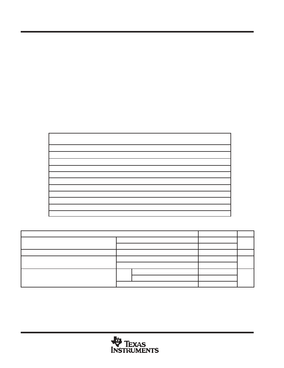
absolute maximum ratings over operating free-air temperature range (unless otherwise noted)
Supply voltage, VDD (see Note 1)
4 V
. . . . . . . . . . . . . . . . . . . . . . . . . . . . . . . . . . . . . . . . . . . . . . . . . . . . . . . . . . . . .
Differential input voltage, VID
±VDD
. . . . . . . . . . . . . . . . . . . . . . . . . . . . . . . . . . . . . . . . . . . . . . . . . . . . . . . . . . . . . . .
Input current, II (any input)
± 10 mA
. . . . . . . . . . . . . . . . . . . . . . . . . . . . . . . . . . . . . . . . . . . . . . . . . . . . . . . . . . . . . .
Output current, IO
± 10 mA
. . . . . . . . . . . . . . . . . . . . . . . . . . . . . . . . . . . . . . . . . . . . . . . . . . . . . . . . . . . . . . . . . . . . . .
Continuous total power dissipation
See Dissipation Rating Table
. . . . . . . . . . . . . . . . . . . . . . . . . . . . . . . . . . . . .
Operating free-air temperature range, TA: C-suffix
0
°C to 70°C
. . . . . . . . . . . . . . . . . . . . . . . . . . . . . . . . . . . . . .
I-suffix
40
°C to 125°C
. . . . . . . . . . . . . . . . . . . . . . . . . . . . . . . . . . .
Maximum junction temperature, TJ
150
°C
. . . . . . . . . . . . . . . . . . . . . . . . . . . . . . . . . . . . . . . . . . . . . . . . . . . . . . . . .
Storage temperature range, Tstg
65
°C to 150°C
. . . . . . . . . . . . . . . . . . . . . . . . . . . . . . . . . . . . . . . . . . . . . . . . . . .
Lead temperature 1,6 mm (1/16 inch) from case for 10 seconds
260
°C
. . . . . . . . . . . . . . . . . . . . . . . . . . . . . . .
Stresses beyond those listed under “absolute maximum ratings” may cause permanent damage to the device. These are stress ratings only, and
functional operation of the device at these or any other conditions beyond those indicated under “recommended operating conditions” is not
implied. Exposure to absolute-maximum-rated conditions for extended periods may affect device reliability.
NOTE 1: All voltage values, except differential voltages, are with respect to GND.
DISSIPATION RATING TABLE
PACKAGE
ΘJC
ΘJA
TA ≤ 25°C
TA = 125°C
PACKAGE
ΘJC
(
°C/W)
ΘJA
(
°C/W)
TA ≤ 25 C
POWER RATING
TA = 125 C
POWER RATING
D (8)
38.3
176
710 mW
142 mW
D (14)
26.9
122.3
1022 mW
204.4 mW
D (16)
25.7
114.7
1090 mW
218 mW
DBV (5)
55
324.1
385 mW
77.1 mW
DBV (6)
55
294.3
425 mW
85 mW
DGK (8)
54.2
259.9
481 mW
96.2 mW
DGS (10)
54.1
257.7
485 mW
97 mW
N (14, 16)
32
78
1600 mW
320.5 mW
P (8)
41
104
1200 mW
240.4 mW
PW (14)
29.3
173.6
720 mW
144 mW
PW (16)
28.7
161.4
774 mW
154.9 mW
recommended operating conditions
MIN
MAX
UNIT
Supply voltage, VDD
Single supply
1.8
3.6
V
Supply voltage, VDD
Split supply
±0.9
±1.8
V
Common-mode input voltage range, VICR
0.2
VDD+0.2
V
Operating free-air temperature, TA
C-suffix
0
70
°C
Operating free-air temperature, TA
I-suffix
40
125
°C
VIH
VDD < 2.7 V
0.75VDD
Shutdown on/off voltage level
VIH
VDD = 2.7 to 3.6 V
2
V
Shutdown on/off voltage level
VIL
0.6
V
Relative to GND.
相關(guān)PDF資料 |
PDF描述 |
|---|---|
| TLV3701CDBV | COMPARATOR, 7000 uV OFFSET-MAX, 240000 ns RESPONSE TIME, PDSO5 |
| TLV3701IDBV | COMPARATOR, 7000 uV OFFSET-MAX, 240000 ns RESPONSE TIME, PDSO5 |
| TLZ9V1C | 9.065 V, 0.5 W, SILICON, UNIDIRECTIONAL VOLTAGE REGULATOR DIODE, DO-213AA |
| TM20DA-H | 31.4 A, 800 V, SCR |
| TM20DA-M | 31.4 A, 400 V, SCR |
相關(guān)代理商/技術(shù)參數(shù) |
參數(shù)描述 |
|---|---|
| TLV2780IDG4 | 功能描述:運算放大器 - 運放 Single 1.8V RRIO 8MHz RoHS:否 制造商:STMicroelectronics 通道數(shù)量:4 共模抑制比(最小值):63 dB 輸入補償電壓:1 mV 輸入偏流(最大值):10 pA 工作電源電壓:2.7 V to 5.5 V 安裝風格:SMD/SMT 封裝 / 箱體:QFN-16 轉(zhuǎn)換速度:0.89 V/us 關(guān)閉:No 輸出電流:55 mA 最大工作溫度:+ 125 C 封裝:Reel |
| TLV2780IDR | 功能描述:運算放大器 - 運放 Single 1.8V RRIO 8MHz RoHS:否 制造商:STMicroelectronics 通道數(shù)量:4 共模抑制比(最小值):63 dB 輸入補償電壓:1 mV 輸入偏流(最大值):10 pA 工作電源電壓:2.7 V to 5.5 V 安裝風格:SMD/SMT 封裝 / 箱體:QFN-16 轉(zhuǎn)換速度:0.89 V/us 關(guān)閉:No 輸出電流:55 mA 最大工作溫度:+ 125 C 封裝:Reel |
| TLV2780IDRG4 | 功能描述:運算放大器 - 運放 Single 1.8V RRIO 8MHz RoHS:否 制造商:STMicroelectronics 通道數(shù)量:4 共模抑制比(最小值):63 dB 輸入補償電壓:1 mV 輸入偏流(最大值):10 pA 工作電源電壓:2.7 V to 5.5 V 安裝風格:SMD/SMT 封裝 / 箱體:QFN-16 轉(zhuǎn)換速度:0.89 V/us 關(guān)閉:No 輸出電流:55 mA 最大工作溫度:+ 125 C 封裝:Reel |
| TLV2780IP | 制造商:Rochester Electronics LLC 功能描述:- Bulk |
| TLV2781AIDR | 制造商:Rochester Electronics LLC 功能描述:- Bulk 制造商:Texas Instruments 功能描述: |
發(fā)布緊急采購,3分鐘左右您將得到回復。