- 您現(xiàn)在的位置:買賣IC網(wǎng) > PDF目錄98244 > TLC5733IPM (TEXAS INSTRUMENTS INC) 3-CH 8-BIT FLASH METHOD ADC, PARALLEL ACCESS, PQFP64 PDF資料下載
參數(shù)資料
| 型號: | TLC5733IPM |
| 廠商: | TEXAS INSTRUMENTS INC |
| 元件分類: | ADC |
| 英文描述: | 3-CH 8-BIT FLASH METHOD ADC, PARALLEL ACCESS, PQFP64 |
| 封裝: | PLASTIC, QFP-64 |
| 文件頁數(shù): | 22/24頁 |
| 文件大?。?/td> | 347K |
| 代理商: | TLC5733IPM |

TLC5733A
20 MSPS 3-CHANNEL ANALOG-TO-DIGITAL CONVERTER
WITH HIGH-PRECISION CLAMP
SLAS104B – JULY 1995 – REVISED FEBRUARY 2001
7
POST OFFICE BOX 655303
DALLAS, TEXAS 75265
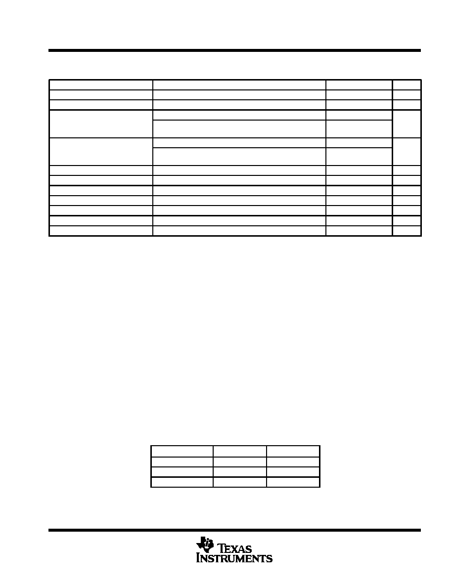
operating characteristics at QnDVDD = 2.7 V to 5.25 V, DVDD = 5 V, VCC = 5 V, Vref(RT) = 2.5 V,
Vref(RB) = 0.5 V, f(CLK) = 20 MHz, TA = 25°C (unless otherwise noted)
PARAMETER
TEST CONDITIONS
MIN
TYP
MAX
UNIT
EZS
Zero-scale error
Vref = REFT – REFB = 2 V
– 18
– 43
– 68
mV
EFS
Full-scale error
Vref = REFT – REFB = 2 V
– 20
0
20
mV
f(CLK) = 20 MHz,
VI = 0.5 V to 2.5 V
±0.4 ±0.75
EL
Linearity error
f(CLK) = 20 MHz,
TA = –20°C to 75°C
VI = 0.5 V to 2.5 V
±0.4
±1
LSB
f(CLK) = 20 MHz,
VI = 0.5 V to 2.5 V
±0.3
±0.5
ED
Linearity error, differential
f(CLK) = 20 MHz,
TA = –20°C to 75°C
VI = 0.5 V to 2.5 V
±0.3 ±0.75
LSB
fc
Maximum conversion rate
VI = 0.5 V – 2.5 V,
fI = 1-kHz ramp waveform
20
MSPS
BW
Analog input bandwidth
At – 1 dB
14
MHz
tpd
Digital output delay time
CL = 10 pF
18
30
ns
Differential gain
NTSC 40 IRE modulation wave,
fc = 14.3 MSPS
1%
Differential phase
NTSC 40 IRE modulation wave,
fc = 14.3 MSPS
0.7
deg
Aperture jitter time
30
ps
Sampling delay time
4
ns
Institute of Radio Engineers
detailed description
clamp function
The clamp function is optimized for a YUV video signal and has two clamp modes. The first mode uses the
COMPOSITE SYNC signal as the input to the EXTCLP terminal to generate an internal clamp pulse and the
second mode uses an externally generated clamp pulse as the input to the EXTCLP terminal.
In the first mode, the device detects false pulses in the COMPOSITE SYNC signal by monitoring the rising and
falling edges of the COMPOSITE SYNC signal pulses. This monitoring prevents faulty operation caused by
disturbances and missing pulses of the COMPOSITE SYNC signal input on EXTCLP and external spike noise.
When fault pulses are detected, the device internally generates a train of clamp pulses at the proper positions
(1H) by an internal 910-counter for NTSC and a 1136-counter for PAL. The device checks clamp pulses for 1H
time and generates clamp pulses at correct positions when COMPOSITE SYNC pulses are in error in time.
The internal counter continually produces a horizontal sync period (1H) that is NTSC or PAL compatible as
selected by the condition of the NT/PAL terminal.
clamp voltages and selection
Table 1 shows the clamping level during the clamp interval. Table 2 shows the selection of the internal or external
clamp pulse. With either NTSC or PAL, the internal clamp pulse is always used.
Table 1. Clamp Level (Internal Connection Level)
CHANNEL OF ADC
OUTPUT CODE
APPLICATION
CHANNEL OF ADC
OUTPUT CODE
APPLICATION
ADC A
VI(A)
00010000
Y
ADC B
VI(B)
10000000
(U, V)
ADC C
VI(C)
10000000
(U, V)
相關(guān)PDF資料 |
PDF描述 |
|---|---|
| TLC7135CFN | 4-BIT DUAL-SLOPE ADC, PARALLEL ACCESS, PQCC28 |
| TLC7135CN | 1-CH 4-BIT DUAL-SLOPE ADC, PARALLEL ACCESS, PDIP28 |
| TLC7135CDWR | 1-CH 4-BIT DUAL-SLOPE ADC, PARALLEL ACCESS, PDSO28 |
| TLC7135CNG4 | 1-CH 4-BIT DUAL-SLOPE ADC, PARALLEL ACCESS, PDIP28 |
| TLC7225CDW | PARALLEL, 8 BITS INPUT LOADING, 8-BIT DAC, PDSO24 |
相關(guān)代理商/技術(shù)參數(shù) |
參數(shù)描述 |
|---|---|
| TLC5902 | 制造商:Rochester Electronics LLC 功能描述:- Bulk |
| TLC59025 | 制造商:TI 制造商全稱:Texas Instruments 功能描述:LOW-POWER 16-CHANNEL CONSTANT-CURRENT LED SINK DRIVER |
| TLC59025IDBQR | 功能描述:LED照明驅(qū)動器 Lo-Pwr 16Ch Const Crnt LED Sink Driver RoHS:否 制造商:STMicroelectronics 輸入電壓:11.5 V to 23 V 工作頻率: 最大電源電流:1.7 mA 輸出電流: 最大工作溫度: 安裝風格:SMD/SMT 封裝 / 箱體:SO-16N |
| TLC59025IDWR | 制造商:TI 制造商全稱:Texas Instruments 功能描述:LOW-POWER 16-CHANNEL CONSTANT-CURRENT LED SINK DRIVER |
| TLC59025IPWR | 制造商:Texas Instruments 功能描述: |
發(fā)布緊急采購,3分鐘左右您將得到回復。