- 您現(xiàn)在的位置:買賣IC網(wǎng) > PDF目錄69492 > TL594IPWRG4 (TEXAS INSTRUMENTS INC) 0.25 A SWITCHING CONTROLLER, 300 kHz SWITCHING FREQ-MAX, PDSO16 PDF資料下載
參數(shù)資料
| 型號(hào): | TL594IPWRG4 |
| 廠商: | TEXAS INSTRUMENTS INC |
| 元件分類: | 穩(wěn)壓器 |
| 英文描述: | 0.25 A SWITCHING CONTROLLER, 300 kHz SWITCHING FREQ-MAX, PDSO16 |
| 封裝: | GREEN, PLASTIC, TSSOP-16 |
| 文件頁(yè)數(shù): | 16/21頁(yè) |
| 文件大小: | 646K |
| 代理商: | TL594IPWRG4 |
第1頁(yè)第2頁(yè)第3頁(yè)第4頁(yè)第5頁(yè)第6頁(yè)第7頁(yè)第8頁(yè)第9頁(yè)第10頁(yè)第11頁(yè)第12頁(yè)第13頁(yè)第14頁(yè)第15頁(yè)當(dāng)前第16頁(yè)第17頁(yè)第18頁(yè)第19頁(yè)第20頁(yè)第21頁(yè)
www.ti.com
s
+
N
n+1
(xn * X)
2
N * 1
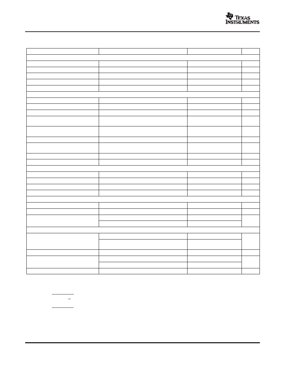
ELECTRICAL CHARACTERISTICS
PULSE-WIDTH-MODULATION CONTROL CIRCUIT
SLVS052G – APRIL 1988 – REVISED JANUARY 2007
V
CC = 15 V, over recommended operating free-air temperature range (unless otherwise noted)
PARAMETER
TEST CONDITIONS(1)
MIN
TYP(2)
MAX
UNIT
Reference Section
Output voltage (REF)
IO = 1 mA, TA = 25°C
4.95
5
5.05
V
Input regulation
VCC = 7 V to 40 V, TA = 25°C
2
25
mV
Output regulation
IO = 1 mA to 10 mA, TA = 25°C
14
35
mV
Output-voltage change with temperature
T
A = MIN to MAX
2
10
mV/V
Short-circuit output current(3)
Vref = 0
10
35
50
mA
Amplifier Section (see Figure 1)
Input offset voltage, error amplifier
FEEDBACK = 2.5 V
2
10
mV
Input offset current
FEEDBACK = 2.5 V
25
250
nA
Input bias current
FEEDBACK = 2.5 V
0.2
1
A
Common-mode input voltage range,
0.3 to
VCC = 7 V to 40 V
V
error amplifier
VCC – 2
Open-loop voltage amplification,
V
O = 3 V, RL = 2 k, VO = 0.5 V to 3.5 V
70
95
dB
error amplifier
Unity-gain bandwidth
VO = 0.5 V to 3.5 V, RL = 2 k
800
kHz
Common-mode rejection ratio,
VCC = 40 V, TA = 25°C
65
80
dB
error amplifier
Output sink current, FEEDBACK
VID = –15 mV to –5 V, FEEDBACK = 0.5 V
0.3
0.7
mA
Output source current, FEEDBACK
VID = 15 mV to 5 V, FEEDBACK = 3.5 V
–2
mA
Frequency
10
kHz
Standard deviation of frequency(4)
All values of VCC, CT, RT, and TA constant
100
Hz/kHz
Frequency change with voltage
VCC = 7 V to 40 V, TA = 25°C
1
Hz/kHz
Frequency change with temperature(5)
T
A = MIN to MAX
50
Hz/kHz
Dead-Time Control Section (see Figure 2)
Input bias current
VI = 0 to 5.25 V
–2
–10
A
Maximum duty cycle, each output
DTC = 0 V
0.45
Zero duty cycle
3
3.3
Input threshold voltage
V
Maximum duty cycle
0
Output Section
VC = 40 V, VE = 0 V, VCC = 40 V
2
100
Collector off-state current
A
DTC and OUTPUT CTRL = 0 V, VC = 15 V,
4
200
VE = 0 V, VCC = 1 V to 3 V
Emitter off-state current
VCC = VC = 40 V, VE = 0
–100
A
Common emitter, VE = 0, IC = 200 mA
1.1
1.3
Collector-emitter saturation voltage
V
Emitter follower, VC = 15 V, IE = –200 mA
1.5
2.5
Output control input current
VI = Vref
3.5
mA
(1)
For conditions shown as MIN or MAX, use the appropriate value specified under recommended operating conditions.
(2)
All typical values, except for parameter changes with temperature, are at TA = 25°C.
(3)
Duration of the short circuit should not exceed one second.
(4)
Standard deviation is a measure of the statistical distribution about the mean, as derived from the formula:
(5)
Temperature coefficient of timing capacitor and timing resistor is not taken into account.
4
相關(guān)PDF資料 |
PDF描述 |
|---|---|
| TL594IPWE4 | 0.25 A SWITCHING CONTROLLER, 300 kHz SWITCHING FREQ-MAX, PDSO16 |
| TL598MFK | 0.25 A SWITCHING CONTROLLER, 300 kHz SWITCHING FREQ-MAX, CQCC20 |
| TL598Y | 0.25 A SWITCHING CONTROLLER, 300 kHz SWITCHING FREQ-MAX, UUC |
| TL7660CPE4 | SWITCHED CAPACITOR CONVERTER, 9 kHz SWITCHING FREQ-MAX, PDIP8 |
| TL7660IDGKRG4 | SWITCHED CAPACITOR CONVERTER, 9 kHz SWITCHING FREQ-MAX, PDSO8 |
相關(guān)代理商/技術(shù)參數(shù) |
參數(shù)描述 |
|---|---|
| TL594L-D16-T | 制造商:UTC-IC 制造商全稱:UTC-IC 功能描述:PULSE-WIDTH-MODULATION CONTROL CIRCUIT |
| TL594L-P16-R | 制造商:UTC-IC 制造商全稱:UTC-IC 功能描述:PULSE-WIDTH-MODULATION CONTROL CIRCUIT |
| TL594L-P16-T | 制造商:UTC-IC 制造商全稱:UTC-IC 功能描述:PULSE-WIDTH-MODULATION CONTROL CIRCUIT |
| TL594L-S16-R | 制造商:UTC-IC 制造商全稱:UTC-IC 功能描述:PULSE-WIDTH-MODULATION CONTROL CIRCUIT |
| TL594L-S16-T | 制造商:UTC-IC 制造商全稱:UTC-IC 功能描述:PULSE-WIDTH-MODULATION CONTROL CIRCUIT |
發(fā)布緊急采購(gòu),3分鐘左右您將得到回復(fù)。