- 您現(xiàn)在的位置:買賣IC網(wǎng) > PDF目錄385924 > THAT2181C (Electronic Theatre Controls, Inc.) Trimmable IC Voltage Controlled Amplifiers PDF資料下載
參數(shù)資料
| 型號: | THAT2181C |
| 廠商: | Electronic Theatre Controls, Inc. |
| 英文描述: | Trimmable IC Voltage Controlled Amplifiers |
| 中文描述: | 微調(diào)IC電壓控制放大器 |
| 文件頁數(shù): | 4/10頁 |
| 文件大?。?/td> | 252K |
| 代理商: | THAT2181C |
THAT Corporation; 45 Sumner Street; Milford, Massachusetts 01757-1656; USA
Tel: +1 508 478 9200; Fax: +1 508 478 0990; Web: www.thatcorp.com
Page 4
THAT2181 Series IC VCAs
Theory of Operation
3
The THAT 2181 Series VCAs are designed for high
performance in audio-frequency applications requiring
exponential gain control, low distortion, wide dynamic
range and low control-voltage feedthrough. These parts
control gain by converting an input current signal to a
bipolar logged voltage, adding a dc control voltage, and
re-converting the summed voltage back to a current
through a bipolar antilog circuit.
Figure 5 presents a considerably simplified internal
circuit diagram of the IC. The ac input signal current
flows in pin1, the input pin. An internal operational
transconductance amplifier (OTA) works to maintain
pin 1 at a virtual ground potential by driving the emitters
of Q1 and (through the Voltage Bias Generator) Q3.
Q3/D3 and Q1/D1 act to log the input current, producing
a voltage, V3, which represents the bipolar logarithm of
the input current. (The voltage at the junction of D1 and
D2 is the same as V3, but shifted by four forward V
be
drops.)
Gain Control
Since pin 8, the output, is usually connected to a vir-
tual ground, Q2/D2 and Q4/D4 take the bipolar antilog
of V3, creating an output current which is a precise rep-
lica of the input current. If pin 2 (Ec+) and pin 3 (Ec-)
are held at ground (with pin 4 - SYM - connected to a
high impedance current source), the output current will
equal the input current. For pin 2 positive or pin 3 nega-
tive, the output current will be scaled larger than the in-
put current. For pin 2 negative or pin 3 positive, the
output current is scaled smaller than the input.
The scale factor between the output and input cur-
rents is the gain of the VCA. Either pin 2 (Ec+) or pin 3
(Ec-), or both, may be used to control gain. Gain is expo-
nentially proportional to the voltage at pin 2, and expo-
nentially proportional to the negative of the voltage at
pin 3. Therefore, pin 2 (Ec+) is the
positive
control port,
while pin 3 (Ec-) is the
negative
control port. Because of
the exponential characteristic, the control voltage sets
gain
linearly
in
decibels
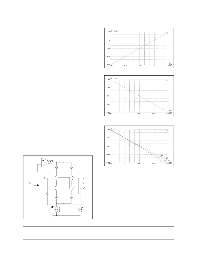
. Figure 6 shows the decibel cur-
rent gain of a 2181 versus the voltage at Ec+, while Fig-
ure 7 shows gain versus the Ec-.
Temperature Effects
The logging and antilogging in the VCA depends on
the logarithmic relationship between voltage and current
in a semiconductor junction (in particular, between a
transistor's V
be
and I
c
). As is well known, this relation-
3. For more details about the internal workings of the 2181 Series of VCAs, see
An Improved Monolithic Volt-
age-Controlled Amplifier
, by Gary K. Hebert (Vice-President, Engineering, for THAT Corporation), presented at the 99th
convention of the Audio Engineering Society, New York, Preprint number 4055.
Figure 6. Gain vs. Control Voltage (E
C+
, Pin 2) at 25 C
Figure 7. Gain vs. Control Voltage (Ec-, Pin 3) at 25 C
Figure 8. Gain vs. Control Voltage (Ec-) with Temp (°C)
D1
IN
OUT
SYM
Ec-
D4
D3
Ec+
25
V-
+
Voltage
Bias
Generator
V
3
I
IN
Q1
Q4
Q3
Q2
Icell
Iadj
5
4
8
3
1
2
D2
Figure 5. Simplified Internal Circuit Diagram
相關(guān)PDF資料 |
PDF描述 |
|---|---|
| THAT300 | Low-Noise Matched Transistor Array ICs |
| THAT300P | Low-Noise Matched Transistor Array ICs |
| THAT300S | Low-Noise Matched Transistor Array ICs |
| THAT320P | Low-Noise Matched Transistor Array ICs |
| THAT320S | Low-Noise Matched Transistor Array ICs |
相關(guān)代理商/技術(shù)參數(shù) |
參數(shù)描述 |
|---|---|
| THAT2181CL08-U | 制造商:THAT CORPORATION 功能描述:AMP VOLT CONTROLLED TRIMMABLE 2181 制造商:THAT CORPORATION 功能描述:AMP, VOLT CONTROLLED, TRIMMABLE, 2181 制造商:THAT CORPORATION 功能描述:AMP, VOLT CONTROLLED, TRIMMABLE, 2181; IC Function:Voltage Controlled Amplifier; Brief Features:Exponential Gain Control, Wide Gain Range; Supply Voltage Min:-18V; Supply Voltage Max:18V; Operating Temperature Min:0C; Operating ;RoHS Compliant: Yes |
| THAT2252 | 制造商:未知廠家 制造商全稱:未知廠家 功能描述:IC RMS-Level Detector |
| THAT2252L08-U | 制造商:THAT CORPORATION 功能描述:DETECTOR RMS LEVEL DETECTOR 2252 制造商:THAT CORPORATION 功能描述:DETECTOR, RMS LEVEL DETECTOR, 2252 制造商:THAT CORPORATION 功能描述:DETECTOR, RMS LEVEL DETECTOR, 2252; Bandwidth:20kHz; Power Dissipation Pd:330mW; Supply Voltage Range: 4V to 15V; Digital IC Case Style:SIP; No. of Pins:8; Supply Current:1mA; Operating Temperature Min:-20C; Operating Temperature;RoHS Compliant: Yes |
| THAT300 | 制造商:未知廠家 制造商全稱:未知廠家 功能描述:Low-Noise Matched Transistor Array ICs |
| THAT300P | 制造商:未知廠家 制造商全稱:未知廠家 功能描述:Low-Noise Matched Transistor Array ICs |
發(fā)布緊急采購,3分鐘左右您將得到回復(fù)。