- 您現(xiàn)在的位置:買賣IC網(wǎng) > PDF目錄371185 > TF1001A LG1602 Decision Circuit PDF資料下載
參數(shù)資料
| 型號: | TF1001A |
| 英文描述: | LG1602 Decision Circuit |
| 中文描述: | LG1602判決電路 |
| 文件頁數(shù): | 4/10頁 |
| 文件大小: | 253K |
| 代理商: | TF1001A |

Data Sheet
February 1999
LG1602 Decision Circuit
4
Lucent Technologies Inc.
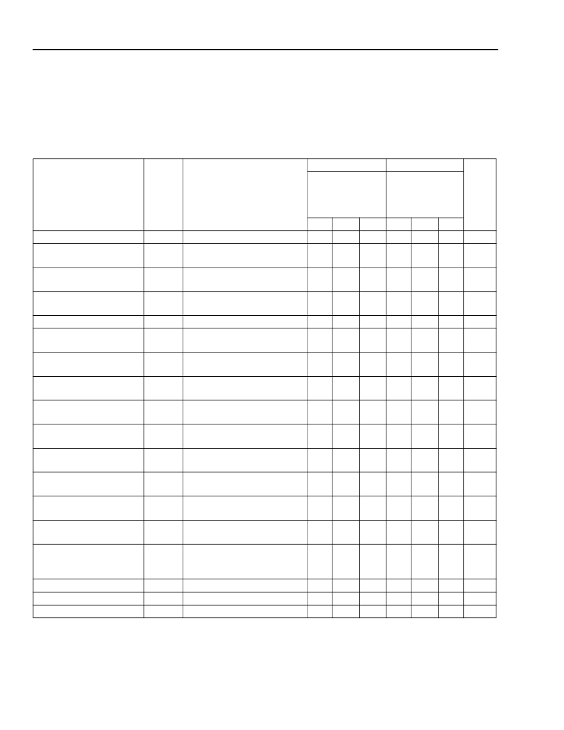
Electrical Characteristics
Bit rate = 2.488 Mbits/s NRZ and data pattern = 2
23
– 1 PRBS, unless otherwise indicated. See Figure 3 for the tim-
ing and signal levels and Figure 5 for the test circuit, when using the TF1001A test fixture.
Note:
Minimum and maximum values are testing requirements. Typical values are characteristics of the device
and are the result of engineering evaluations. Typical values are for information purposes only and are not
part of the testing requirements.
Parameter
Symbol
Conditions
LG1602AXB
t
CASE =
25 °C
V
SS
= –5.2 V
LG1602BXB
t
CASE =
0 °C—
75 °C
V
SS
= –4.9 V to
–5.5 V
Min
Typ
2.5
—
200
—
Unit
Min
3
200
Typ
—
—
Max
—
800
Max
—
900
Maximum Bit Rate
Data Input Voltage
|
V
H
– <V>
|
+
|
<V> – V
L
|
Data Input Sensitivity
—
—
BER = 10
–9
GHz
mV
t
R
, t
F
≤
165 ps (20%—80%)
—
BER = 10
–9
, limited clock
phase margin
t
R
, t
F
≤
85 ps (20%—80%),
duty cycle = 50% ± 10%
—
Data transition to negative
edge of CLOCK IN
Data transition to negative
edge of CLOCK IN
Data transition to negative
edge of CLOCK IN
Valid input data to negative
edge of CLOCK IN
Negative edge CLOCK IN to
valid DATA IN
CLOCK IN negative edge to
output transition
Outputs ac coupled (see
Figure 5)
20%—80%, outputs ac cou-
pled
1 MHz—2 GHz, outputs ac
coupled
100 kHz—300 kHz
0.3 MHz—1500 MHz
1.5 GHz—1.8 GHz
2.4 GHz—2.6 GHz
—
Junction to case bottom
—
20
—
—
20
—
mV
Clock Input Voltage
|
V
H
– <V>
|
+
|
<V> – V
L
|
Clock Phase Margin
Clock Phase Minimum
—
500
—
1000 200
—
900
mV
—
t1
250
—
360
—
—
—
250
—
360
150
—
205
ps
ps
Clock Phase Maximum
t2
—
—
—
455
510
—
ps
Clock Phase Center
t
C
—
330
—
—
330
—
ps
Setup Time
t
S
—
185
—
—
185
205
ps
Hold Time
t
H
—
–73
—
—
–73
–53
ps
Propagation Delay
t
PD
—
1200
—
—
1200
—
ps
Output Voltage (V
H
– V
L
)
—
500
600
—
500
600
—
mV
Output Transition Time
—
—
—
100
—
—
100
ps
Output Return Loss
—
—
15
—
—
15
—
dB
Data Input Return Loss
—
—
—
—
—
—
—
10
15
15
15
115
20
—
—
—
—
—
—
10
15
15
15
—
—
—
—
—
—
115
20
—
—
—
—
—
—
dB
dB
dB
dB
mA
°C/W
Clock Input Return Loss
Power Supply Current
Thermal Resistance
—
—
—
相關PDF資料 |
PDF描述 |
|---|---|
| TF1003C | LG1605DXB Limiting Amplifier |
| TF1004A | LG1600FXH Clock and Data Regenerator |
| TF1006A | LG1625AXF Laser Driver |
| TFA9841J | 1-channel audio amplifier |
| TFA9843J | 2-channel audio amplifier (SE: 1 W to 20 W or BTL: 4 W to 40 W) |
相關代理商/技術參數(shù) |
參數(shù)描述 |
|---|---|
| TF1003C | 制造商:AGERE 制造商全稱:AGERE 功能描述:LG1605DXB Limiting Amplifier |
| TF1004A | 制造商:AGERE 制造商全稱:AGERE 功能描述:LG1600FXH Clock and Data Regenerator |
| TF100-5 | 制造商:RHOMBUS-IND 制造商全稱:Rhombus Industries Inc. 功能描述:TF Series High Performance 20 Section 10-Tap Delay Lines / SP3 Series |
| TF100505 | 制造商:FRONTIER 制造商全稱:Frontier Electronics. 功能描述:Tape and Reel Specifications |
| TF100505-10NJ | 制造商:FRONTIER 制造商全稱:Frontier Electronics. 功能描述:Multi-layers Chip Inductors |
發(fā)布緊急采購,3分鐘左右您將得到回復。