- 您現(xiàn)在的位置:買(mǎi)賣(mài)IC網(wǎng) > PDF目錄371183 > TDA9181 (NXP Semiconductors N.V.) Integrated multistandard comb filter PDF資料下載
參數(shù)資料
| 型號(hào): | TDA9181 |
| 廠商: | NXP Semiconductors N.V. |
| 英文描述: | Integrated multistandard comb filter |
| 中文描述: | 集成多標(biāo)準(zhǔn)梳狀濾波器 |
| 文件頁(yè)數(shù): | 6/32頁(yè) |
| 文件大小: | 135K |
| 代理商: | TDA9181 |
第1頁(yè)第2頁(yè)第3頁(yè)第4頁(yè)第5頁(yè)當(dāng)前第6頁(yè)第7頁(yè)第8頁(yè)第9頁(yè)第10頁(yè)第11頁(yè)第12頁(yè)第13頁(yè)第14頁(yè)第15頁(yè)第16頁(yè)第17頁(yè)第18頁(yè)第19頁(yè)第20頁(yè)第21頁(yè)第22頁(yè)第23頁(yè)第24頁(yè)第25頁(yè)第26頁(yè)第27頁(yè)第28頁(yè)第29頁(yè)第30頁(yè)第31頁(yè)第32頁(yè)
2000 Nov 22
6
Philips Semiconductors
Objective specification
Integrated multistandard comb filter
TDA9181
Mode definitions
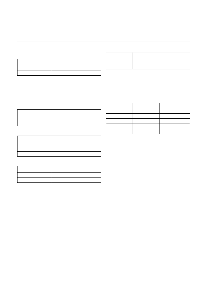
Table 1
General mode definitions; note 1
Note
1.
If the OUTSEL pin is left open-circuit, the pin is pulled
LOW by means of an internal pull-down resistor to
analog ground (AGND). Thus the COMB mode can
also be selected by not connecting the OUTSEL pin.
Table 2
Y/CVBS
OUT
output signal definitions
Table 3
C
OUT
output signal definitions
Table 4
Input switch mode definitions; note 1
Note
1.
If the INPSEL pin is left open-circuit, the pin is pulled
LOW by means of an internal pull-down resistor to
analog ground (AGND). Thus the Y/CVBS
1
input can
also be selected by not connecting the INPSEL pin.
Table 5
FSC mode definitions; note 1
Note
1.
If the FSCSEL pin is left open-circuit, the pin is pulled
LOW by means of an internal pull-down resistor to
analog ground (AGND). Thus the f
SC
mode can also
be selected by not connecting the FSCSEL pin.
Table 6
Video standard mode definitions; note 1
Note
1.
If the SYS1 and SYS2 pins are left open-circuit, the
SYS1 pin is pulled HIGH by means of an internal
pull-up resistor to analog supply (V
CCA
) and the SYS2
pin is pulled LOW by means of an internal pull-down
resistor to analog ground (AGND). Thus the NTSC M
video standard can also be selected by not connecting
pins SYS1 and SYS2.
PIN OUTSEL
MODE
LOW
HIGH
COMB
YC
MODE
Y/CVBS
OUT
OUTPUT SIGNAL
comb filtered luminance signal
Y/CVBS
1
or Y/CVBS
2
signal
COMB
YC
MODE
C
OUT
OUTPUT SIGNAL
comb filtered chrominance
signal
C
IN
signal
COMB
YC
PIN INPSEL
INPUT SWITCH MODE
LOW
HIGH
Y/CVBS
1
input selected
Y/CVBS
2
input selected
PIN FSCSEL
FSC INPUT SIGNAL FREQUENCY
LOW
HIGH
f
SC
2
×
f
SC
PIN SYS1
PIN SYS2
VIDEO
STANDARD
LOW
LOW
HIGH
HIGH
LOW
HIGH
LOW
HIGH
PAL M
PAL B, G, H, D or I
NTSC M
PAL N
發(fā)布緊急采購(gòu),3分鐘左右您將得到回復(fù)。