- 您現(xiàn)在的位置:買賣IC網(wǎng) > PDF目錄373621 > TDA7335 (意法半導(dǎo)體) STEREO PREAMP AMS DOLBY B* NOISE REDUCTION PROCESSOR PDF資料下載
參數(shù)資料
| 型號: | TDA7335 |
| 廠商: | 意法半導(dǎo)體 |
| 元件分類: | 音頻放大器 |
| 英文描述: | STEREO PREAMP AMS DOLBY B* NOISE REDUCTION PROCESSOR |
| 中文描述: | 立體聲前置放大器醫(yī)療輔助隊杜比B *降噪處理器 |
| 文件頁數(shù): | 7/20頁 |
| 文件大小: | 427K |
| 代理商: | TDA7335 |
AUDIO MUSIC SENSOR (See Figure2)
Aim of this section is to detect interprogram
spaces present on a recordedtape.
Both the blanks (interprogram spaces) and the
programs minimum detectable durations can be
easily set by means of 2 external and inde-
pendent time constants.
Also the minimum detectable input signal level
can be externally adjusted, by a dedicated gain
network.
Main blocksare:
Variablegain limiteramplifier
Signal detector circuitry
Logicblocksableto avoidunproperoperations.
Operations Description (refer to the simplified
schematic of Figure 2).
a)The two channels left and right mean signal
coming from the preamp chain (AC coupled)
are added (current)at the AMSinput and pre-
sented to the limiter amplifier. The limiter am-
plifier gain is internally fixed to 40dB, and it
could be reduced by the R8 external resistor.
The AMSVth threshold is fixed at 1V. The fol-
lowing signal detector comparator informs of
the presence of music signal (High level out)
and avoids the erroneous detection of very
low signal (like noise) as real program.
b)The system moves in blank detection mode
everytime the supply is turned on or, with
power supplied, the AMS On/Off pin (to be
driven by an open collector output) is turned
off (T
1
open). Once this condition has hap-
pened, the capacitor C
15
charges, defining a
minimum reset time, long enough to reset the
Flip-Flops FF
1
and FF
2
and to descharge the
program detector external C
7
capacitor. The
charging current at the AMS SW pin is about
10
μ
A. It follows that the reset time (C
15 x
V
pin8
)/I
C15
is given approximately by 0.122
x
C
15
ns where C
15
is in
μ
F.
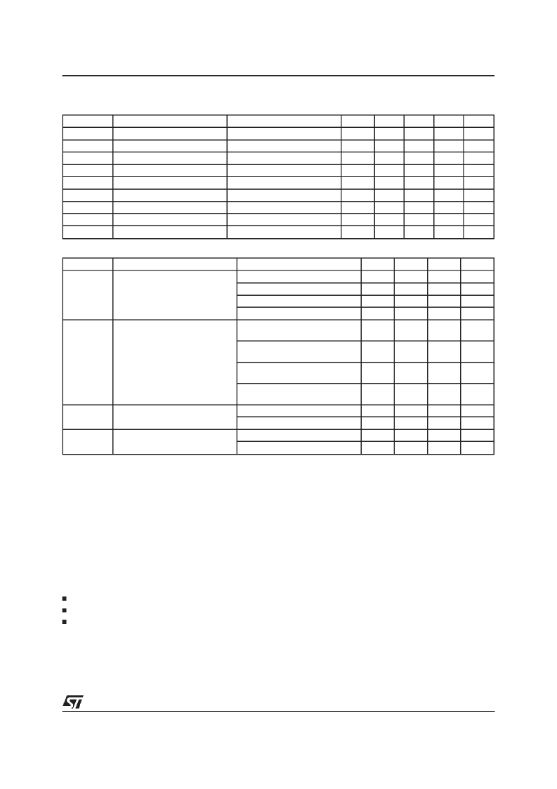
ELECTRICALCHARACTERISTICS
(continued)
DOLBY SECTION
Symbol
RD
O
S/H
B DEC 1
B DEC 2
B DEC 3
B DEC 4
B DEC 5
NR
l
NR
h
GENERAL (PREAMPLIFIER + DOLBY)
Parameter
Test Condition
(pin 13, 18)
V
S
= 8V;THD = 1%
f = 10KHz;V
I
= 0.4dB
f = 500Hz; V
I
= -22.1dB
f = 2KHz;V
I
= -18dB
f = 5KHz;V
I
= -29.7dB
f = 10KHz;V
I
= -29.6dB
DOLBY
Min.
100
12
-1.5
-26.5
-26.5
-41.5
-41.5
0
2
Typ.
200
13
0
-25
-25
-40
-40
Max.
300
Unit
dB
dB
dB
dB
dB
dB
V
V
Dolby Output Impedance
Signal Handling
Decode Out
Decode Out
Decode Out
Decode Out
Decode Out
DolbyONLowLevel Pin20
Dolby OFF High Level Pin20
OFF
ON
ON
ON
ON
ON
1.5
-23.5
-23.5
-38.5
-38.5
0.8
V
S
Symbol
THD
Parameter
Test Condition
V
O
= 0dB; f = 1KHz Dolby OFF
V
O
= 0dB; f = 1KHz Dolby ON
V
O
= 0dB; f = 10KHz Dolby OFF
V
O
= 0dB; f = 10KHz Dolby ON
R
g
= 600
; V
O
= 0dB;
Unweighted; Dolby OFF
R
g
= 600
; V
O
= 0dB;
Unweighted; Dolby ON
R
g
=600
;V
O
= 0dB;
CCIR/ARM; Dolby OFF
R
g
=600
;V
O
= 0dB;
CCIR/ARM; Dolby ON
R
g
= 600
; f = 1KHz Dolby OFF
R
g
= 600
; f = 1KHz Dolby ON
R
g
= 600
; f = 1KHz Dolby OFF
R
g
= 600
; f = 1KHz Dolby ON
Min.
Typ.
0.02
0.05
0.03
0.08
63
Max.
0.1
0.1
Unit
%
%
%
%
dB
Total Harmonic Dist.
S/N
Signal to Noise Ratio
70
dB
54
63
dB
56
72
dB
C
S
Channel Separation
50
64
70
70
75
dB
dB
dB
dB
C
T
Channel Cross Talk
56
TDA7335
7/20
相關(guān)PDF資料 |
PDF描述 |
|---|---|
| TDA7336 | STEREO PREAMP+ AMS+ DOLBY B* NOISE REDUCTION PROCESSOR |
| TDA7338 | STEREO DECODER |
| TDA7338D | STEREO DECODER |
| TDA7339 | 3 BAND DIGITAL CONTROLLED AUDIO PROCESSOR |
| TDA7340G | AUDIO SIGNAL PROCESSOR |
相關(guān)代理商/技術(shù)參數(shù) |
參數(shù)描述 |
|---|---|
| TDA7336 | 制造商:STMICROELECTRONICS 制造商全稱:STMicroelectronics 功能描述:STEREO PREAMP+ AMS+ DOLBY B* NOISE REDUCTION PROCESSOR |
| TDA7338 | 制造商:STMICROELECTRONICS 制造商全稱:STMicroelectronics 功能描述:STEREO DECODER |
| TDA7338_05 | 制造商:STMICROELECTRONICS 制造商全稱:STMicroelectronics 功能描述:STEREO DECODER |
| TDA7338D | 功能描述:接口—CODEC Stereo Decoder RoHS:否 制造商:Texas Instruments 類型: 分辨率: 轉(zhuǎn)換速率:48 kSPs 接口類型:I2C ADC 數(shù)量:2 DAC 數(shù)量:4 工作電源電壓:1.8 V, 2.1 V, 2.3 V to 5.5 V 最大工作溫度:+ 85 C 安裝風(fēng)格:SMD/SMT 封裝 / 箱體:DSBGA-81 封裝:Reel |
| TDA7338D013TR | 功能描述:接口—CODEC Stereo Decoder RoHS:否 制造商:Texas Instruments 類型: 分辨率: 轉(zhuǎn)換速率:48 kSPs 接口類型:I2C ADC 數(shù)量:2 DAC 數(shù)量:4 工作電源電壓:1.8 V, 2.1 V, 2.3 V to 5.5 V 最大工作溫度:+ 85 C 安裝風(fēng)格:SMD/SMT 封裝 / 箱體:DSBGA-81 封裝:Reel |
發(fā)布緊急采購,3分鐘左右您將得到回復(fù)。