- 您現(xiàn)在的位置:買(mǎi)賣(mài)IC網(wǎng) > PDF目錄98170 > TC642BEOA713 BRUSHLESS DC MOTOR CONTROLLER, PDSO8 PDF資料下載
參數(shù)資料
| 型號(hào): | TC642BEOA713 |
| 元件分類(lèi): | 運(yùn)動(dòng)控制電子 |
| 英文描述: | BRUSHLESS DC MOTOR CONTROLLER, PDSO8 |
| 封裝: | 0.150 INCH, PLASTIC, SOIC-8 |
| 文件頁(yè)數(shù): | 16/34頁(yè) |
| 文件大小: | 683K |
| 代理商: | TC642BEOA713 |
第1頁(yè)第2頁(yè)第3頁(yè)第4頁(yè)第5頁(yè)第6頁(yè)第7頁(yè)第8頁(yè)第9頁(yè)第10頁(yè)第11頁(yè)第12頁(yè)第13頁(yè)第14頁(yè)第15頁(yè)當(dāng)前第16頁(yè)第17頁(yè)第18頁(yè)第19頁(yè)第20頁(yè)第21頁(yè)第22頁(yè)第23頁(yè)第24頁(yè)第25頁(yè)第26頁(yè)第27頁(yè)第28頁(yè)第29頁(yè)第30頁(yè)第31頁(yè)第32頁(yè)第33頁(yè)第34頁(yè)

2003 Microchip Technology Inc.
DS21756B-page 23
TC642B/TC647B
Step 2: Selecting the Fan Controller.
The requirements for the fan controller are that it have
minimum speed capability at 20C and also indicate a
fan fault condition. No over-temperature indication is
necessary. Based on these specifications, the proper
selection is the TC647B device.
Step 3: Setting the PWM Frequency.
The fan is rated at 4200 RPM with a 12V input. Since
the goal is to run to a 40% duty cycle (roughly 40% fan
speed), which equates to approximately 1700 RPM,
we can assume one full fan revolution occurs every
35 msec. The fan being used is a four-pole fan that
gives four current pulses per revolution. Knowing this
and viewing test results at 40% duty cycle, two fan cur-
rent pulses were always seen during the PWM on time
with a PWM frequency of 30 Hz. For this reason, the CF
value is selected to be 1.0
F.
Step 4: Setting the VIN Voltage.
From the design criteria, the desired duty cycle at 20C
is 40%, while full fan speed should be reached at 40C.
Based on a VIN voltage range of 1.20V to 2.60V, which
represents 0% to 100% duty cycle, the 40% duty cycle
voltage can be found using the following equation:
EQUATION
Using the above equation, the VIN values are
calculated to be:
-VIN (40%) = 1.76V
-VIN (100%) = 2.60V
Using these values in combination with the thermistor
resistance values calculated earlier, the R1 and R2
resistor values can now be calculated using the
following equation:
EQUATION
RTEMP is the parallel combination of R1 and the ther-
mistor. V(T1) represents the VIN voltage at 20C and
V(T2) represents the VIN voltage at 40C. Solving the
equations simultaneously yields the following values
(VDD = 5V):
-R1 = 238,455
-R2 = 45,161
Using standard 1% resistor values, the selected R1 and
R2 values are:
-R1 = 237 k
-R2 = 45.3 k
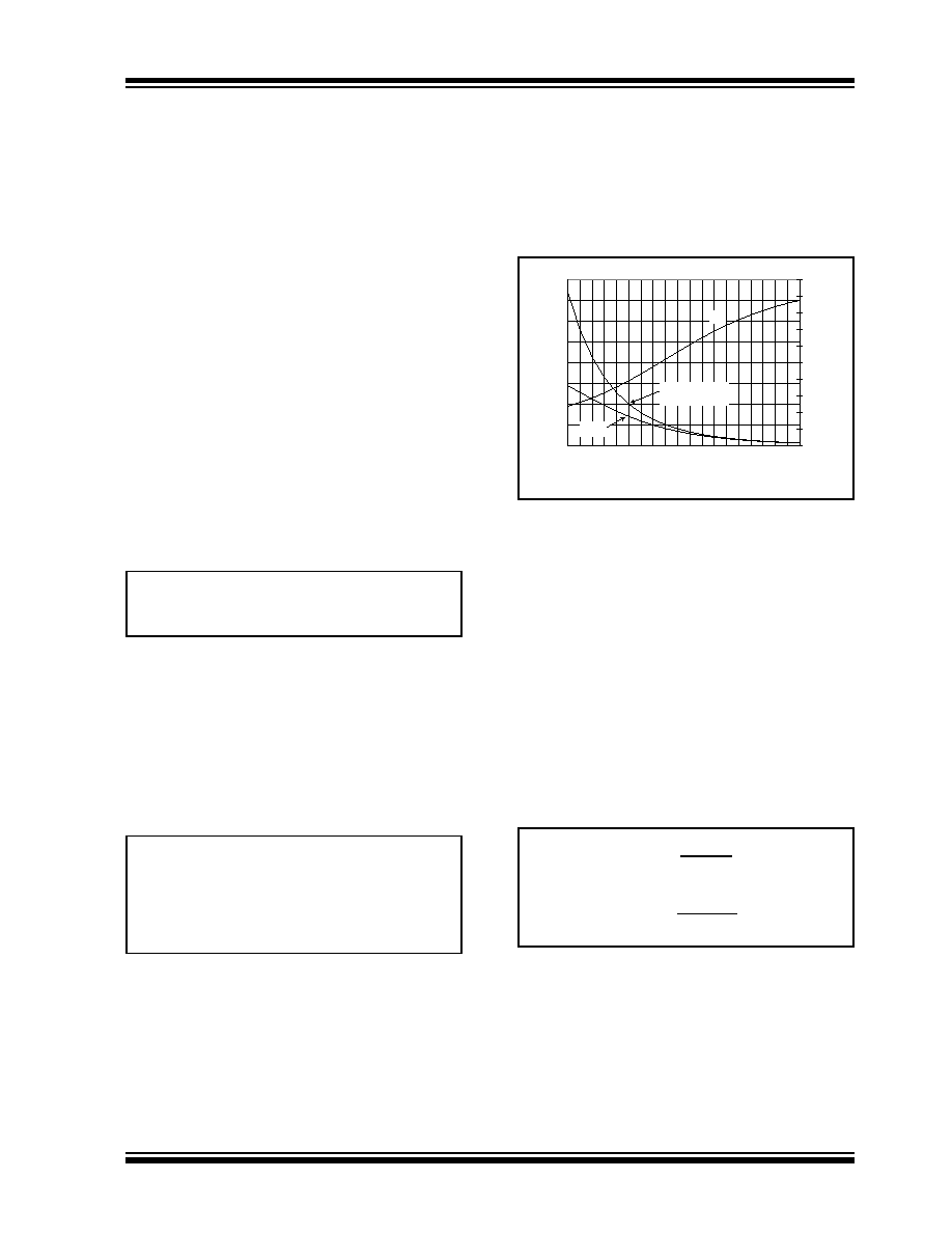
A graph of the VIN voltage, thermistor resistance and
RTEMP resistance versus temperature for this
configuration is shown in Figure 5-10.
FIGURE 5-10:
Thermistor Resistance, VIN,
and RTEMP vs. Temperature.
Step 5: Setting the Minimum Speed Voltage (VMIN).
Setting the voltage for the minimum speed is accom-
plished using a simple resistor voltage divider. The cri-
teria for the voltage divider in this design is that it draw
no more than 100 A of current. The required minimum
speed voltage was determined earlier in the selection
of the VIN voltage at 40% duty cycle, since this was also
set at the temperature which minimum speed is to
occur (20C).
-VMIN = 1.76V
Given this desired setpoint, and knowing the desired
divider current, the following equations can be used to
solve for the resistor values for R3 and R4:
EQUATION
Using the equations above, the resistor values for R3
and R4 are found to be:
-R3 = 32.4 k
-R4 = 17.6 k
VIN = (DC * 1.4V) + 1.20V
DC = Desired Duty Cycle
VT1
()
VDD R2
×
RTEMP T1
() R2
+
------------------------------------------
=
VT2
()
VDD R2
×
RTEMP T2
() R2
+
------------------------------------------
=
0
50
100
150
200
250
300
350
400
0
1020
3040
5060
7080
90
Temperature (C)
Network
Resistance
(k
)
0.00
0.50
1.00
1.50
2.00
2.50
3.00
3.50
4.00
4.50
5.00
V
IN
(V)
VIN
NTC Thermistor
100 k @ 25C
RTEMP
VMIN =
5V*R4
R3 + R4
IDIV =
5V
R3 + R4
相關(guān)PDF資料 |
PDF描述 |
|---|---|
| TC647BEUA | BRUSHLESS DC MOTOR CONTROLLER, PDSO8 |
| TC642BEOA | BRUSHLESS DC MOTOR CONTROLLER, PDSO8 |
| TC647EOATR | BRUSHLESS DC MOTOR CONTROLLER, PDSO8 |
| TC647VUATR | BRUSHLESS DC MOTOR CONTROLLER, PDSO8 |
| TC647VOART | BRUSHLESS DC MOTOR CONTROLLER, PDSO8 |
相關(guān)代理商/技術(shù)參數(shù) |
參數(shù)描述 |
|---|---|
| TC642BEOAG | 制造商:Microchip Technology 功能描述:Fan Control Demo Board |
| TC642BEOATR | 制造商:MICROCHIP 制造商全稱(chēng):Microchip Technology 功能描述:PWM Fan Speed Controllers With Minimum Fan Speed, Fan Restart and FanSense⑩ Technology for Fault Detection |
| TC642BEPA | 功能描述:馬達(dá)/運(yùn)動(dòng)/點(diǎn)火控制器和驅(qū)動(dòng)器 w/Rstrt & Flt Dtct RoHS:否 制造商:STMicroelectronics 產(chǎn)品:Stepper Motor Controllers / Drivers 類(lèi)型:2 Phase Stepper Motor Driver 工作電源電壓:8 V to 45 V 電源電流:0.5 mA 工作溫度:- 25 C to + 125 C 安裝風(fēng)格:SMD/SMT 封裝 / 箱體:HTSSOP-28 封裝:Tube |
| TC642BEPA713 | 制造商:MICROCHIP 制造商全稱(chēng):Microchip Technology 功能描述:PWM Fan Speed Controllers With Minimum Fan Speed, Fan Restart and FanSense⑩ Technology for Fault Detection |
| TC642BEPATR | 制造商:MICROCHIP 制造商全稱(chēng):Microchip Technology 功能描述:PWM Fan Speed Controllers With Minimum Fan Speed, Fan Restart and FanSense⑩ Technology for Fault Detection |
發(fā)布緊急采購(gòu),3分鐘左右您將得到回復(fù)。