- 您現(xiàn)在的位置:買賣IC網(wǎng) > PDF目錄361374 > TC4427COA (Microchip Technology Inc.) 1.5A DUAL HIGH-SPEED POWER MOSFET DRIVERS PDF資料下載
參數(shù)資料
| 型號: | TC4427COA |
| 廠商: | Microchip Technology Inc. |
| 英文描述: | 1.5A DUAL HIGH-SPEED POWER MOSFET DRIVERS |
| 中文描述: | 1.5A的雙高速功率MOSFET驅動器 |
| 文件頁數(shù): | 1/6頁 |
| 文件大?。?/td> | 75K |
| 代理商: | TC4427COA |

4-245
TELCOM SEMICONDUCTOR, INC.
7
6
5
4
3
1
2
8
1.5A DUAL HIGH-SPEED, POWER MOSFET DRIVERS
TC4426
TC4427
TC4428
OUTPUT
INPUT
GND
EFFECTIVE INPUT
C = 12 pF
300 mV
INVERTING
OUTPUTS
NONINVERTING
OUTPUTS
V
DD
TC4426/TC4427/TC4428
4.7V
NOTES:
1.TC4426 has 2 inverting drivers; TC4427 has 2 noninverting drivers.
2. TC4428 has one inverting and one noninverting driver.
3. Ground any unused driver input.
FEATURES
I
I
I
High Peak Output Current ............................... 1.5A
Wide Operating Range ..........................4.5V to 18V
High Capacitive Load
Drive Capability ........................ 1000 pF in 25 nsec
Short Delay Time ................................ <40nsec Typ
Consistent Delay Times With Changes in
Supply Voltage
Low Supply Current
— With Logic “1” Input .................................... 4mA
— With Logic “0” Input ................................. 400
μ
A
Low Output Impedance ....................................... 7
Latch-Up Protected: Will Withstand >0.5A
Reverse Current................................. Down to – 5V
Input Will Withstand Negative Inputs
ESD Protected.....................................................4kV
Pinout Same as TC426/TC427/TC428
I
I
I
I
I
I
I
I
GENERAL DESCRIPTION
The TC4426/4427/4428 are improved versions of the
earlier TC426/427/428 family of buffer/drivers (with which
they are pin compatible). They will not latch up under any
conditions within their power and voltage ratings. They are
not subject to damage when up to 5V of noise spiking (of
either polarity) occurs on the ground pin. They can accept,
without damage or logic upset, up to 500mA of reverse
current (of either polarity) being forced back into their
outputs. All terminals are fully protected against up to 4kV of
electrostatic discharge.
As MOSFET drivers, the TC4426/4427/4428 can easily
switch 1000 pF gate capacitances in under 30nsec, and
provide low enough impedances in both the ON and OFF
states to ensure the MOSFET's intended state will not be
affected, even by large transients.
Other compatible drivers are the TC4426A/27A/28A.
These drivers have matched input to output leading edge
and falling edge delays, tD1 and tD2, for processing short
duration pulses in the 25 nanoseconds range. They are pin
compatible with the TC4426/27/28.
TC4426/7/8-8 10/21/96
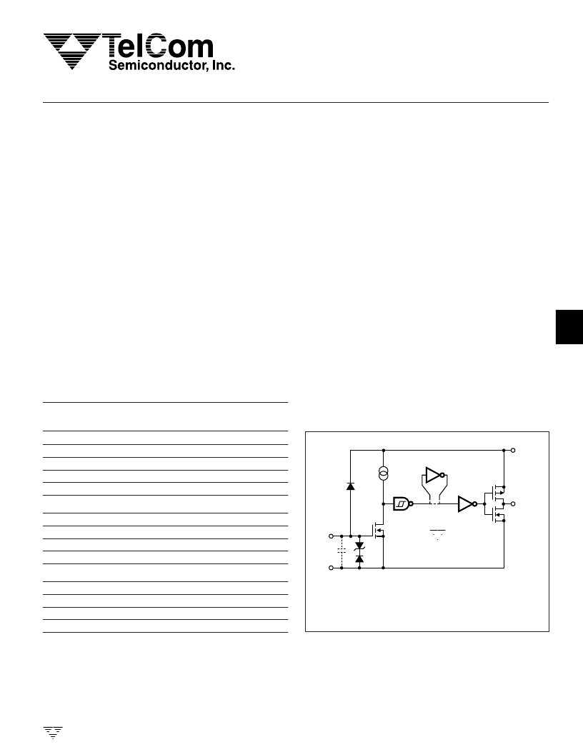
FUNCTIONAL BLOCK DIAGRAM
ORDERING INFORMATION
Temperature
Range
Part No.
Package
TC4426COA
TC4426CPA
TC4426EOA
TC4426EPA
TC4426MJA
8-Pin SOIC
8-Pin Plastic DIP
8-Pin SOIC
8-Pin Plastic DIP
8-Pin CerDIP
0
°
C to +70
°
C
0
°
C to +70
°
C
– 40
°
C to +85
°
C
– 40
°
C to +85
°
C
– 55
°
C to +125
°
C
TC4427COA
TC4427CPA
TC4427EOA
TC4427EPA
TC4427MJA
8-Pin SOIC
8-Pin Plastic DIP
8-Pin SOIC
8-Pin Plastic DIP
8-Pin CerDIP
0
°
C to +70
°
C
0
°
C to +70
°
C
– 40
°
C to +85
°
C
– 40
°
C to +85
°
C
– 55
°
C to +125
°
C
TC4428COA
TC4428CPA
TC4428EOA
TC4428EPA
TC4428MJA
8-Pin SOIC
8-Pin Plastic DIP
8-Pin SOIC
8-Pin Plastic DIP
8-Pin CerDIP
0
°
C to +70
°
C
0
°
C to +70
°
C
– 40
°
C to +85
°
C
– 40
°
C to +85
°
C
– 55
°
C to +125
°
C
相關PDF資料 |
PDF描述 |
|---|---|
| TC4427CPA | 1.5A DUAL HIGH-SPEED POWER MOSFET DRIVERS |
| TC4426MJA | 1.5A DUAL HIGH-SPEED POWER MOSFET DRIVERS |
| TC4427 | 1.5A DUAL HIGH-SPEED POWER MOSFET DRIVERS |
| TC4428EPA | 1.5A DUAL HIGH-SPEED POWER MOSFET DRIVERS |
| TC4426 | 1.5A DUAL HIGH-SPEED POWER MOSFET DRIVERS |
相關代理商/技術參數(shù) |
參數(shù)描述 |
|---|---|
| TC4427COA | 制造商:Microchip Technology Inc 功能描述:1.5A MOSFET DRIVER DUAL SMD 4427 |
| TC4427COA713 | 功能描述:功率驅動器IC 1.5A Dual RoHS:否 制造商:Micrel 產(chǎn)品:MOSFET Gate Drivers 類型:Low Cost High or Low Side MOSFET Driver 上升時間: 下降時間: 電源電壓-最大:30 V 電源電壓-最小:2.75 V 電源電流: 最大功率耗散: 最大工作溫度:+ 85 C 安裝風格:SMD/SMT 封裝 / 箱體:SOIC-8 封裝:Tube |
| TC4427CPA | 功能描述:功率驅動器IC 1.5A Dual MOSFET Dr NonInver Ctemp PDIP8 RoHS:否 制造商:Micrel 產(chǎn)品:MOSFET Gate Drivers 類型:Low Cost High or Low Side MOSFET Driver 上升時間: 下降時間: 電源電壓-最大:30 V 電源電壓-最小:2.75 V 電源電流: 最大功率耗散: 最大工作溫度:+ 85 C 安裝風格:SMD/SMT 封裝 / 箱體:SOIC-8 封裝:Tube |
| TC4427CPA | 制造商:Microchip Technology Inc 功能描述:FET DRIVER DUAL 1.5A 4427 DIP8 |
| TC4427CPA | 制造商:Microchip Technology Inc 功能描述:IC MOSFET DRIVER LOW SIDE DIP-8 |
發(fā)布緊急采購,3分鐘左右您將得到回復。