- 您現(xiàn)在的位置:買賣IC網(wǎng) > PDF目錄98163 > TAS5424TDKDRQ1 (TEXAS INSTRUMENTS INC) 116 W, 4 CHANNEL, AUDIO AMPLIFIER, PDSO44 PDF資料下載
參數(shù)資料
| 型號: | TAS5424TDKDRQ1 |
| 廠商: | TEXAS INSTRUMENTS INC |
| 元件分類: | 音頻/視頻放大 |
| 英文描述: | 116 W, 4 CHANNEL, AUDIO AMPLIFIER, PDSO44 |
| 封裝: | GREEN, PLASTIC, HSSOP-44 |
| 文件頁數(shù): | 42/43頁 |
| 文件大?。?/td> | 978K |
| 代理商: | TAS5424TDKDRQ1 |
第1頁第2頁第3頁第4頁第5頁第6頁第7頁第8頁第9頁第10頁第11頁第12頁第13頁第14頁第15頁第16頁第17頁第18頁第19頁第20頁第21頁第22頁第23頁第24頁第25頁第26頁第27頁第28頁第29頁第30頁第31頁第32頁第33頁第34頁第35頁第36頁第37頁第38頁第39頁第40頁第41頁當前第42頁第43頁

www.ti.com
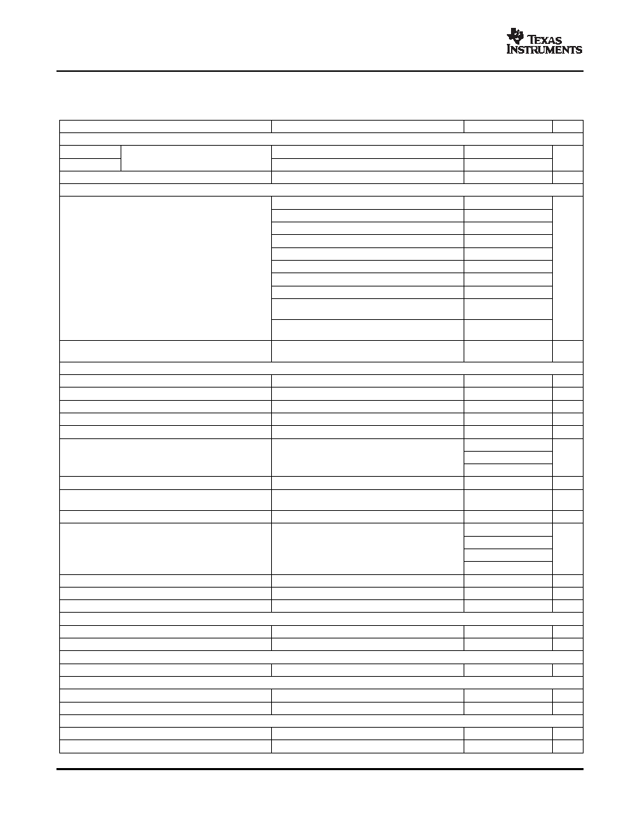
ELECTRICAL CHARACTERISTICS
SLOS514A – FEBRUARY 2007 – REVISED JULY 2007
Test conditions (unless otherwise noted): TCase = 25°C, PVDD = 14.4 V, RL = 4 , fS = 417 kHz, Rext = 20 k, master mode
operation (see application diagram)
PARAMETER
TEST CONDITIONS
MIN
TYP
MAX
UNIT
OPERATING CURRENT
IPVDD_IDLE
All four channels running in MUTE mode
240
300
PVDD idle current
mA
IPVDD_Hi-Z
All four channels in Hi-Z mode
80
IPVDD_STBY
PVDD standby current
STANDBY mode, TJ ≤ 85°C
2
20
μA
OUTPUT POWER
4
, PVDD = 14.4V, THD+N ≤ 1%, 1 kHz, T
c = 75°C
23
4
, PVDD = 14.4V, THD+N = 10%, 1 kHz, T
c = 75°C
25
28
4
, PVDD = 14.4V, square wave, 1 kHz, T
c = 75°C
43
4
, PVDD = 21 V, THD+N = 1%, 1 kHz, T
c = 75°C
47
4
, PVDD = 21 V, THD+N = 10%, 1 kHz, T
c = 75°C
50
58
2
, PVDD = 14.4V, THD+N = 1%, 1 kHz, T
c = 75°C
38
POUT
Output power per channel
W
2
, PVDD = 14.4V, THD+N = 10%, 1 kHz, T
c = 75°C
40
45
2
, PVDD = 14.4 V, square wave 1 kHz, T
c = 75°C
70
PBTL 2-
operation, PVDD = 21 V, THD+N = 10%,
116
1 kHz, Tc = 75°C
PBTL 1-
operation, PVDD = 14.4 V, THD+N = 10%,
90
1 kHz, Tc = 75°C
4 channels operating, 23W output power/ch, L = 10
μH,
EFFP
Power efficiency
90%
TJ ≤ 85°C
AUDIO PERFORMANCE
VNOISE
Noise voltage at output
G = 26 dB, zero input, AES17 filter, and A-weighting
60
100
μV
Crosstalk
Channel crosstalk
1W, G = 26 dB, 1 kHz
60
75
dB
CMRR5424
Common-mode rejection ratio (TAS5424)
1 kHz, 1 Vrms referenced to SGND, G = 26 dB
60
75
dB
PSRR
Power supply rejection ratio
G = 26 dB, PVDD = 14.4 Vdc + 1 Vrms, f = 1 kHz
60
75
dB
THD+N
Total harmonic distortion + noise
P = 1 W, G = 26 dB, f = 1 kHz, 0
°C ≤ T
J ≤ 75°C
0.02%
0.1%
336
357
378
Switching frequency selectable for AM interference
fS
Switching frequency
392
417
442
kHz
avoidance
470
500
530
RAIN
Analog input resistance
Internal shunt resistance on each input pin
60
80
100
k
AC-coupled common-mode input voltage (zero
VIN_CM
Common-mode input voltage (non-clipping)
1.3
Vrms
differential input)
VCM_INT
Internal common-mode input bias voltage
Internal bias applied to IN_M pin
3.25
V
11
12
13
19
20
21
G
Voltage gain (VO/VIN)
Source impedance = 0
dB
25
26
27
31
32
33
GCH
Channel-to-channel variation
Any gain commanded
–1
0
1
dB
tCM
Output-voltage common-mode ramping time
35
ms
tGAIN
Gain ramping time
External CMUTE = 330 nF
30
ms
PWM OUTPUT STAGE
RDSon
FET Drain-to-source resistance
Not including bond wire resistance, TJ = 25°C
75
95
m
VO_OFFSET
Output offset voltage
Zero input signal and G = 26 dB
±10
±25
mV
PVDD OVER VOLTAGE (OV) PROTECTION
VOV
PVDD over voltage shutdown
22.1
23.7
26.3
V
LOAD DUMP (LD) PROTECTION
VLD_SD_SET
Load-dump shutdown voltage
26.6
29
32
V
VLD_SD_CLEAR
Recovery voltage for load-dump shutdown
23.5
26.4
28.4
V
PVDD UNDER VOLTAGE (UV) PROTECTION
VUV_SET
PVDD under voltage shutdown
6.5
7
7.5
V
VUV_CLEAR
Recovery voltage for PVDD UV
7
7.5
8
V
8
相關PDF資料 |
PDF描述 |
|---|---|
| TAS5424TDKDQ1G4 | 116 W, 4 CHANNEL, AUDIO AMPLIFIER, PDSO44 |
| TAS5424TDKDRQ1G4 | 116 W, 4 CHANNEL, AUDIO AMPLIFIER, PDSO44 |
| TAS5414TDKDQ1 | 116 W, 4 CHANNEL, AUDIO AMPLIFIER, PDSO36 |
| TAS5414TDKDRQ1 | 116 W, 4 CHANNEL, AUDIO AMPLIFIER, PDSO36 |
| TAS5414TDKDQ1G4 | 116 W, 4 CHANNEL, AUDIO AMPLIFIER, PDSO36 |
相關代理商/技術參數(shù) |
參數(shù)描述 |
|---|---|
| TAS5424TDKDRQ1G4 | 功能描述:音頻放大器 4 Ch Auto Dig Amp RoHS:否 制造商:STMicroelectronics 產(chǎn)品:General Purpose Audio Amplifiers 輸出類型:Digital 輸出功率: THD + 噪聲: 工作電源電壓:3.3 V 電源電流: 最大功率耗散: 最大工作溫度: 安裝風格:SMD/SMT 封裝 / 箱體:TQFP-64 封裝:Reel |
| TAS5504 | 制造商:TI 制造商全稱:Texas Instruments 功能描述:4 Channel Digital Audio PWM Processor |
| TAS5504_06 | 制造商:TI 制造商全稱:Texas Instruments 功能描述:4 Channel Digital Audio PWM Processor |
| TAS5504-5142V4EVM | 功能描述:音頻 IC 開發(fā)工具 AMPLIFIER MODULE RoHS:否 制造商:Texas Instruments 產(chǎn)品:Evaluation Kits 類型:Audio Amplifiers 工具用于評估:TAS5614L 工作電源電壓:12 V to 38 V |
| TAS5504A | 制造商:TI 制造商全稱:Texas Instruments 功能描述:4-Channel Digital Audio PWM Processor |
發(fā)布緊急采購,3分鐘左右您將得到回復。