- 您現(xiàn)在的位置:買賣IC網(wǎng) > PDF目錄373555 > TA8696F (Toshiba Corporation) TOSHIBA Bipolar Linear Integrated Circuit Silicon Monolithic PDF資料下載
參數(shù)資料
| 型號: | TA8696F |
| 廠商: | Toshiba Corporation |
| 英文描述: | TOSHIBA Bipolar Linear Integrated Circuit Silicon Monolithic |
| 中文描述: | 東芝雙極線性集成電路硅單片 |
| 文件頁數(shù): | 7/12頁 |
| 文件大小: | 210K |
| 代理商: | TA8696F |

TA8696F
2002-02-13
7
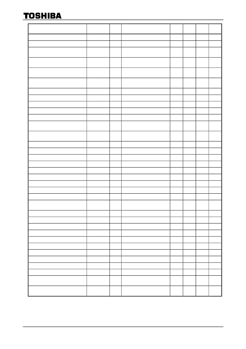
Characteristics
Symbol
Test
Circuit
Test Condition
Min
Typ.
Max
Unit
Gain control sensitivity
2
6
dB/V
Polarity reverse center voltage
2
V
o
center pin open
6.3
6.5
6.7
V
Polarity reverse center voltage
difference in the axes
2
50
100
mV
Polarity reverse center voltage
variable range
2
2
V
Polarity reverse center voltage
controlling sensitivity
2
1
V/V
Typical cut-off level (N.W)
2
Difference from V
o
center
voltage
4.8
5
5.2
V
Cut-off level difference in the axes
2
50
100
mV
Cut-off level variable amount
2
4
V
Cut-off level controlling sensitivity
2
2
V/V
Output dynamic range
2
10
V
p-p
Output impedance
2
10
Frequency characteristic
2
Loaded amount 120 pF, 3dB
point
3
4
MHz
Frequency characteristic difference in
the axes
2
Loaded amount 120 pF, 3dB
point
0.1
0.3
MHz
Slew rate
2
Loaded amount 120 pF
4
V/ s
Slew rate difference in the axes
2
Loaded amount 120 pF
10
%
Crosstalk in the axes
2
50
40
dB
Direct current transmission rate
2
100
%
S/N N
2
40
50
dB
CH indication signal threshold
2
2.2
V
CH indication mode switch threshold
2
2.2
V
CH indication output delay (line mode)
2
1
s
CH indication output delay (dot mode)
2
0.1
s
CH indication latch minimum
operation voltage
2
3
V
HD pulse threshold
2
1.3
1.6
1.9
V
LD pulse threshold
2
1.3
1.6
1.9
V
VD pulse threshold
2
1.3
1.6
1.9
V
F.F. minimum operation voltage
2
10
V
F.F. phase delay
2
3
s
F.F. response frequency
2
20
kHz
F.F. output high level
2
11.0
13.0
V
F.F. output low level
2
0.1
0.3
0.5
V
correction value (1) NW
2
0.35
correction value (2) NW
2
20
correction value difference in the
axes (1)
2
10
%
correction value difference in the
axes (2)
2
10
%
相關(guān)PDF資料 |
PDF描述 |
|---|---|
| TA8703 | QUASI-SIF SYSTEM FOR TV |
| TA8703S | QUASI-SIF SYSTEM FOR TV |
| TA8710 | SIF CONVERTER FOR TV AND VTR |
| TA8710S | DIODE - ULTRAFAST 600V 1A SMA (0.115 X 0.220) |
| TA8712N | PIF QIF SYSTEM FOR TV |
相關(guān)代理商/技術(shù)參數(shù) |
參數(shù)描述 |
|---|---|
| TA-8700 | 制造商:FLORIDA MISC. 功能描述: |
| TA8700AN | 制造商:TOSHIBA 制造商全稱:Toshiba Semiconductor 功能描述:PIF/SIF IC FOR TV/VTR |
| TA8701AN | 制造商:TOSHIBA 制造商全稱:Toshiba Semiconductor 功能描述:PIF/SIF + ATT IC FOR TV/VTR |
| TA8703 | 制造商:TOSHIBA 制造商全稱:Toshiba Semiconductor 功能描述:QUASI-SIF SYSTEM FOR TV |
| TA8703S | 制造商:Panasonic Industrial Company 功能描述:IC |
發(fā)布緊急采購,3分鐘左右您將得到回復(fù)。