- 您現(xiàn)在的位置:買(mǎi)賣(mài)IC網(wǎng) > PDF目錄373541 > TA1276AFG (Toshiba Corporation) PAL/NTSC Video Chroma And Deflection IC For CTV PDF資料下載
參數(shù)資料
| 型號(hào): | TA1276AFG |
| 廠商: | Toshiba Corporation |
| 英文描述: | PAL/NTSC Video Chroma And Deflection IC For CTV |
| 中文描述: | PAL / NTSC制式視頻色度和偏轉(zhuǎn)集成電路為視 |
| 文件頁(yè)數(shù): | 34/83頁(yè) |
| 文件大小: | 1539K |
| 代理商: | TA1276AFG |
第1頁(yè)第2頁(yè)第3頁(yè)第4頁(yè)第5頁(yè)第6頁(yè)第7頁(yè)第8頁(yè)第9頁(yè)第10頁(yè)第11頁(yè)第12頁(yè)第13頁(yè)第14頁(yè)第15頁(yè)第16頁(yè)第17頁(yè)第18頁(yè)第19頁(yè)第20頁(yè)第21頁(yè)第22頁(yè)第23頁(yè)第24頁(yè)第25頁(yè)第26頁(yè)第27頁(yè)第28頁(yè)第29頁(yè)第30頁(yè)第31頁(yè)第32頁(yè)第33頁(yè)當(dāng)前第34頁(yè)第35頁(yè)第36頁(yè)第37頁(yè)第38頁(yè)第39頁(yè)第40頁(yè)第41頁(yè)第42頁(yè)第43頁(yè)第44頁(yè)第45頁(yè)第46頁(yè)第47頁(yè)第48頁(yè)第49頁(yè)第50頁(yè)第51頁(yè)第52頁(yè)第53頁(yè)第54頁(yè)第55頁(yè)第56頁(yè)第57頁(yè)第58頁(yè)第59頁(yè)第60頁(yè)第61頁(yè)第62頁(yè)第63頁(yè)第64頁(yè)第65頁(yè)第66頁(yè)第67頁(yè)第68頁(yè)第69頁(yè)第70頁(yè)第71頁(yè)第72頁(yè)第73頁(yè)第74頁(yè)第75頁(yè)第76頁(yè)第77頁(yè)第78頁(yè)第79頁(yè)第80頁(yè)第81頁(yè)第82頁(yè)第83頁(yè)
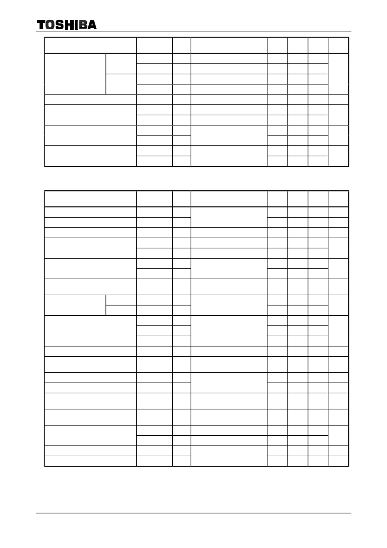
TA1276AFG
2002-04-01
34
Characteristics
Symbol
Test
Circuit
Test Condition
Min
Typ.
Max
Unit
θ
TR
MAX
R
29
33
37
Max
θ
TB
MAX
B
29
33
37
θ
TR
MIN
R
37
33
29
Base band tint control
characteristic
Min
θ
TB
MIN
B
37
33
29
°
Flesh color characteristic
Fa33
(Note A
7
)
0.38
0.48
0.58
DR
R-Y
0.9
1.2
1.5
Color difference signal input dynamic
range
DR
B-Y
0.9
1.2
1.5
V
p-p
GCD0
15.0
18.0
21.0
Color detail emphasis characteristic
GCD1
(Note A
8
)
15.0
0.0
V
p-p
θ
I
→
U
θ
Q
→
V
31
33
35
Phase shift at IQ
→
UV conversion
31
33
35
°
DEF Section
Characteristics
Symbol
Test
Circuit
Test Condition
Min
Typ.
Max
Unit
32f
H
VCO oscillation start voltage
V
VCO
3.1
3.4
3.7
V
Horizontal output start voltage
VH
ON23
DEF V
CC
Voltage
4.7
5.0
5.3
V
Horizontal output duty cycle
T
23
Pin 41
38.5
40.5
42.5
%
f
H050
Vertical freq.; Auto
15475 15625 15775
Horizontal output free-run frequency
f
H060
Vertical freq.; 60 Hz
15585 15734 15885
Hz
f
HMIN
14700 15000 15300
Variable range of horizontal output
frequency
f
HMAX
Variable pin 45 voltage
16500 16700 16900
Hz
Horizontal output frequency control
sensitivity
β
H
(Note D
1
)
180
230
280
Hz/
0.1 V
High level
V
H23
2.7
3.0
3.3
Horizontal output voltage
Low level
V
L23
Pin 40
0.15
0.30
V
SPH1
11.1
11.3
11.5
SPH2
0.35
0.45
0.55
Horizontal output phase
SPH3
(Note D
2
)
0.11
0.21
0.31
V
Curve correction characteristic
H
24
(Note D
3
)
2.3
2.5
2.7
V
Variable range of horizontal picture
position
H
SFT
(Note D
4
)
5.7
6.2
6.7
V
Clamp pulse start phase
CP
S
2.8
2.9
3.1
V
Clamp pulse width
CP
W
(Note D
5
)
1.0
1.2
1.4
V
Threshold of external clamp pulse
input
CP
V30
Pin 40
3.3
3.6
3.9
V
Threshold of external clamp mode
switching
CPM
V23
Pin 41
8.5
8.7
8.9
V
BPv17
Pin 49, at normal scan
0.9
1.1
1.3
Threshold of external black peak hold
stopping pulse
BPv24
Pin 40, at doble scan
0.9
1.1
1.3
SPC gate pulse start phase
GP
S
1.9
2.1
2.3
μ
s
SPC gate pulse width
GP
W
(Note D
6
)
1.9
2.1
2.3
μ
s
相關(guān)PDF資料 |
PDF描述 |
|---|---|
| TA1276AN | TOSHIBA BIPOLAR LINEAR INTEGRATED CIRCUIT SILICON MONOLITHIC |
| TA1281 | UHF/VHF TUNER IC |
| TA1281F | UHF/VHF TUNER IC |
| TA1281FN | UHF/VHF TUNER IC |
| TA1281FA | UHF/VHF TUNER IC |
相關(guān)代理商/技術(shù)參數(shù) |
參數(shù)描述 |
|---|---|
| TA1276AN | 制造商:Panasonic Industrial Company 功能描述:IC 制造商:Toshiba America Electronic Components 功能描述:Tv/Video Signal Proce or Toshiba IC 56-Pin DIP-S |
| TA1281 | 制造商:TOSHIBA 制造商全稱(chēng):Toshiba Semiconductor 功能描述:UHF/VHF TUNER IC |
| TA1281F | 制造商:TOSHIBA 制造商全稱(chēng):Toshiba Semiconductor 功能描述:UHF/VHF TUNER IC |
| TA1281FA | 制造商:TOSHIBA 制造商全稱(chēng):Toshiba Semiconductor 功能描述:UHF/VHF TUNER IC |
| TA1281FN | 制造商:TOSHIBA 制造商全稱(chēng):Toshiba Semiconductor 功能描述:UHF/VHF TUNER IC |
發(fā)布緊急采購(gòu),3分鐘左右您將得到回復(fù)。