- 您現(xiàn)在的位置:買賣IC網(wǎng) > PDF目錄373534 > T89C51RD2-DDSC-L (Atmel Corp.) 0 to 40MHz Flash Programmable 8-bit Microcontroller PDF資料下載
參數(shù)資料
| 型號: | T89C51RD2-DDSC-L |
| 廠商: | Atmel Corp. |
| 英文描述: | 0 to 40MHz Flash Programmable 8-bit Microcontroller |
| 中文描述: | 0至40MHz可編程閃存8位微控制器 |
| 文件頁數(shù): | 31/170頁 |
| 文件大小: | 1927K |
| 代理商: | T89C51RD2-DDSC-L |
第1頁第2頁第3頁第4頁第5頁第6頁第7頁第8頁第9頁第10頁第11頁第12頁第13頁第14頁第15頁第16頁第17頁第18頁第19頁第20頁第21頁第22頁第23頁第24頁第25頁第26頁第27頁第28頁第29頁第30頁當(dāng)前第31頁第32頁第33頁第34頁第35頁第36頁第37頁第38頁第39頁第40頁第41頁第42頁第43頁第44頁第45頁第46頁第47頁第48頁第49頁第50頁第51頁第52頁第53頁第54頁第55頁第56頁第57頁第58頁第59頁第60頁第61頁第62頁第63頁第64頁第65頁第66頁第67頁第68頁第69頁第70頁第71頁第72頁第73頁第74頁第75頁第76頁第77頁第78頁第79頁第80頁第81頁第82頁第83頁第84頁第85頁第86頁第87頁第88頁第89頁第90頁第91頁第92頁第93頁第94頁第95頁第96頁第97頁第98頁第99頁第100頁第101頁第102頁第103頁第104頁第105頁第106頁第107頁第108頁第109頁第110頁第111頁第112頁第113頁第114頁第115頁第116頁第117頁第118頁第119頁第120頁第121頁第122頁第123頁第124頁第125頁第126頁第127頁第128頁第129頁第130頁第131頁第132頁第133頁第134頁第135頁第136頁第137頁第138頁第139頁第140頁第141頁第142頁第143頁第144頁第145頁第146頁第147頁第148頁第149頁第150頁第151頁第152頁第153頁第154頁第155頁第156頁第157頁第158頁第159頁第160頁第161頁第162頁第163頁第164頁第165頁第166頁第167頁第168頁第169頁第170頁
31
A/T89C51CC01
4129L–CAN–08/05
Registers
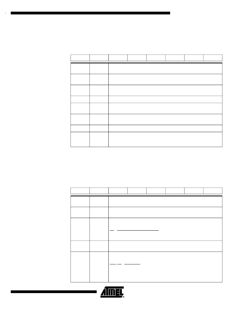
Table 18.
PSW Register
PSW (S:D0h)
Program Status Word Register
Reset Value = 0000 0000b
Table 19.
AUXR Register
AUXR (S:8Eh)
Auxiliary Register
7
6
5
4
3
2
1
0
CY
AC
F0
RS1
RS0
OV
F1
P
Bit
Number
Bit
Mnemonic
Description
7
CY
Carry Flag
Carry out from bit 1 of ALU operands.
6
AC
Auxiliary Carry Flag
Carry out from bit 1 of addition operands.
5
F0
User Definable Flag 0.
4-3
RS1:0
Register Bank Select Bits
Refer to Table 16 for bits description.
2
OV
Overflow Flag
Overflow set by arithmetic operations.
1
F1
User Definable Flag 1
0
P
Parity Bit
Set when ACC contains an odd number of 1’s.
Cleared when ACC contains an even number of 1’s.
7
6
5
4
3
2
1
0
-
-
M0
-
XRS1
XRS0
EXTRAM
A0
Bit
Number
Bit
Mnemonic
Description
7-6
-
Reserved
The value read from these bits are indeterminate. Do not set this bit.
5
M0
Stretch MOVX control:
the RD/ and the WR/ pulse length is increased according to the value of M0.
M0
Pulse length in clock period
0
6
1
30
4
-
Reserved
The value read from this bit is indeterminate. Do not set this bit.
3-2
XRS1-0
XRAM size:
Accessible size of the XRAM
XRS 1:0 XRAM size
0
0 256 Bytes
0 1 512 Bytes
1
0
768 Bytes
1
1
1024 Bytes (default)
發(fā)布緊急采購,3分鐘左右您將得到回復(fù)。