- 您現(xiàn)在的位置:買賣IC網(wǎng) > PDF目錄11652 > SX8723E083TRT (Semtech)IC DAS PRESSURE/TEMP SENS 12MLPD PDF資料下載
參數(shù)資料
| 型號(hào): | SX8723E083TRT |
| 廠商: | Semtech |
| 文件頁數(shù): | 7/53頁 |
| 文件大?。?/td> | 0K |
| 描述: | IC DAS PRESSURE/TEMP SENS 12MLPD |
| 標(biāo)準(zhǔn)包裝: | 1 |
| 系列: | ZoomingADC™ |
| 類型: | 數(shù)據(jù)采集系統(tǒng)(DAS) |
| 輸入類型: | 差分 |
| 輸出類型: | 數(shù)字 |
| 接口: | I²C |
| 安裝類型: | 表面貼裝 |
| 封裝/外殼: | 12-BFDFN 裸露焊盤 |
| 供應(yīng)商設(shè)備封裝: | 12-MLPD |
| 包裝: | 標(biāo)準(zhǔn)包裝 |
| 其它名稱: | SX8723E083DKR |
第1頁第2頁第3頁第4頁第5頁第6頁當(dāng)前第7頁第8頁第9頁第10頁第11頁第12頁第13頁第14頁第15頁第16頁第17頁第18頁第19頁第20頁第21頁第22頁第23頁第24頁第25頁第26頁第27頁第28頁第29頁第30頁第31頁第32頁第33頁第34頁第35頁第36頁第37頁第38頁第39頁第40頁第41頁第42頁第43頁第44頁第45頁第46頁第47頁第48頁第49頁第50頁第51頁第52頁第53頁
ADVANCED COMMUNICATIONS & SENSING
V1.8 2009 Semtech Corp.
www.semtech.com
15
SX8723
ZoomingADC for Pressure and Temperature Sensing
ZoomingADC
Features
The ZoomingADC is a complete and versatile low-power analog front-end interface typically intended for sensing
applications.
In the following text the ZoomingADC will be referred as ZADC.
The key features of the ZADC are:
Programmable 6 to 16-bit dynamic range over-sampled ADC
Flexible gain programming between 0.5 and 1000
Flexible and large range offset compensation
3-channel differential or 5-channel single-ended input
2-channel differential reference inputs
Power saving modes
Overview
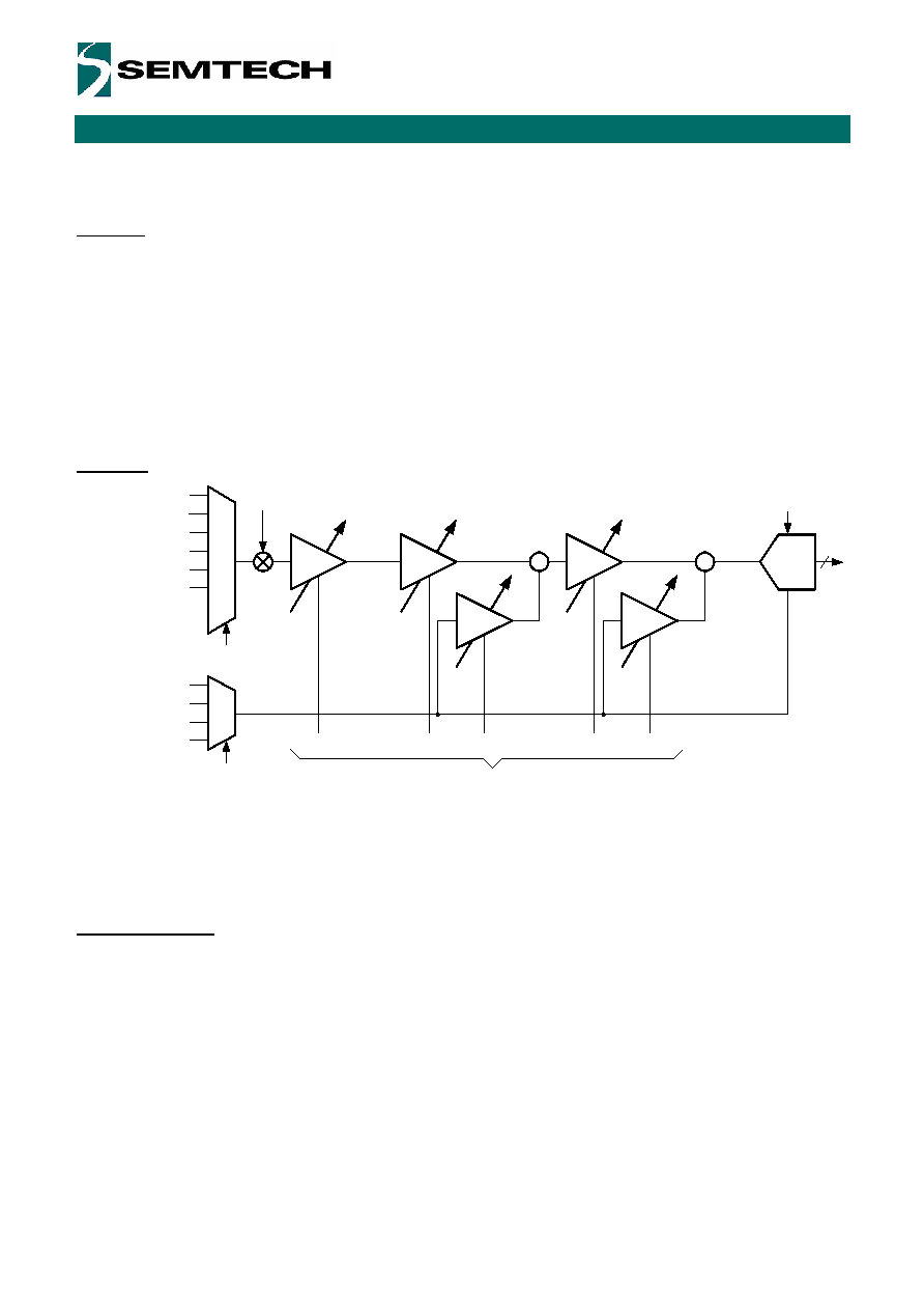
Figure 8 - ZADC General Functional Block Diagram
The total acquisition chain consists of an input multiplexer, 3 programmable gain amplifier stages and an over
sampled A/D converter. The reference voltage can be selected on two different channels. Two offset compensation
amplifiers allow for a wide offset compensation range. The programmable gain and offset allow the application to
zoom in on a small portion of the reference voltage defined input range.
ZADC Description
Acquisition Chain
Figure 8 shows the general block diagram of the acquisition chain (AC). A control block (not shown in Figure 8)
manages all communications with the 2-WIRE peripheral. The clocking is derived from the internal 4 MHz
Oscillator.
Analog inputs can be selected through a 6 input multiplexer, while reference input is selected between two differential
channels. It should however be noted that only 5 acquisition channels (including the VREF) are available when
configured as single ended since the input amplifier is always operating in differential mode with both positive and
negative input selected through the multiplexer.
The core of the zooming section is made of three differential programmable amplifiers (PGA). After selection of an
input and reference signals
VIN and VREF,ADC combination, the input voltage is modulated and amplified through
Input
Selection
Analog
Inputs
Reference
Selection
Reference
Inputs
GD1
OFF2
GD2
OFF3
GD3
+
-
+
-
ADC
f
s
f
s
V
IN
V
D1
V
D2
V
IN,ADC
V
REF,ADC
PGA1
PGA2
PGA3
Gain 1
Gain 2
Offset 2
Gain 3
Offset 3
V
SS
V
REF
AC
2
AC
3
AC
4
AC
5
V
SS
V
BATT
V
SS
V
REF
AC
0
AC
1
-
+
-
+
ZOOM
16
相關(guān)PDF資料 |
PDF描述 |
|---|---|
| MC9S12XA512CAA | IC MCU 512K FLASH 80-QFP |
| A5367CA | IC SMOKE DETECTOR ION 16-DIP |
| A5366CA-T | IC SMOKE DETECTOR PHOTO 16-DIP |
| A5366CA | IC SMOKE DETECTOR PHOTO 16-DIP |
| MCIMX233CAG4B | MPU 32BIT I.MX233 IND 128LQFP |
相關(guān)代理商/技術(shù)參數(shù) |
參數(shù)描述 |
|---|---|
| SX8723S | 制造商:SEMTECH 制造商全稱:Semtech Corporation 功能描述:ZoomingADC for sensing data acquisition |
| SX8723SWLTDT | 制造商:Semtech Corporation 功能描述:2 INPUTS ZOOMING ADC WITH SPI |
| SX8724 | 制造商:SEMTECH 制造商全稱:Semtech Corporation 功能描述:ZoomingADC? for Pressure and Temperature Sensing |
| SX8724C | 制造商:SEMTECH 制造商全稱:Semtech Corporation 功能描述:ZoomingADC for sensing data acquisition |
| SX8724CEVK | 制造商:Semtech Corporation 功能描述: |
發(fā)布緊急采購,3分鐘左右您將得到回復(fù)。