- 您現(xiàn)在的位置:買賣IC網(wǎng) > PDF目錄385879 > SW-276T1 High Power GaAs SPDT Switch DC - 3.0 GHz PDF資料下載
參數(shù)資料
| 型號(hào): | SW-276T1 |
| 英文描述: | High Power GaAs SPDT Switch DC - 3.0 GHz |
| 中文描述: | 高功率GaAs SPDT開關(guān)直流- 3.0吉赫 |
| 文件頁數(shù): | 2/5頁 |
| 文件大?。?/td> | 126K |
| 代理商: | SW-276T1 |
High Power GaAs SPDT Switch
DC - 3.0 GHz
SW-276
M/A-COM Inc. and its affiliates reserve the right to make changes to the
product(s) or information contained herein without notice. M/A-COM makes
no warranty, representation or guarantee regarding the suitability of its
products for any particular purpose, nor does M/A-COM assume any liability
whatsoever arising out of the use or application of any product(s) or
information.
North America
Tel: 800.366.2266 / Fax: 978.366.2266
Europe
Tel: 44.1908.574.200 / Fax: 44.1908.574.300
Asia/Pacific
Tel: 81.44.844.8296 / Fax: 81.44.844.8298
Visit www.macom.com
for additional data sheets and product information.
V3
2
RoHS
Compliant
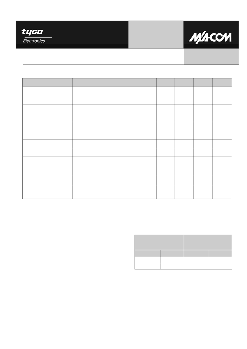
Electrical Specifications: T
A
= -55 to +85°C, Z
0
= 50
Ω
7,8
Parameter
Test Conditions
Units
Min.
Typ.
Max.
Insertion Loss
DC - 0.5 GHz
DC - 1.0 GHz
DC - 2.0 GHz
DC - 3.0 GHz
dB
dB
dB
dB
—
—
—
—
0.4
0.5
0.7
0.9
0.5
0.65
0.8
1.0
Isolation
DC - 0.5 GHz
DC - 1.0 GHz
DC - 2.0 GHz
DC - 3.0 GHz
dB
dB
dB
dB
37
31
24
19
—
—
—
—
—
—
—
—
VSWR
DC - 0.5 GHz
DC - 1.0 GHz
DC - 2.0 GHz
DC - 3.0 GHz
Ratio
Ratio
Ratio
Ratio
—
—
—
—
—
—
—
—
1.3:1
1.5:1
1.5:1
1.6:1
Trise, Tfall
10% to 90% RF, 90% to 10% RF
nS
—
30
—
Ton, Toff
50% control to 90% RF, and 50% control to 10% RF
nS
—
35
—
Transients
In Band
mV
—
12
—
Input Power for P0.1dB
0.9 GHz (-5 V Control)
0.9 GHz (-8 V Control)
dBm
dBm
—
—
32
35
—
—
Third Order Intercept Point
Two +10 dBm Input tones
0.9 GHz (-5 V Control)
0.9 GHz (-8 V Control)
dBm
dBm
—
—
61
65
—
—
Input Power for P1dB
0.9 GHz (-5 V Control)
0.9 GHz (-8 V Control)
dBm
dBm
—
—
35
39
—
—
7. All specifications apply when operated with bias voltages of 0 V for V
IN
Low and -5 to -10 V for V
IN
High, and 50 ohm impedance at all RF
ports, unless otherwise specified.
8. High power (greater than 1W) handling specifications apply to cold switching only. For input powers under 1W hot switching can be used.
Handling Procedures
Please observe the following precautions to avoid
damage:
Static Sensitivity
Gallium Arsenide Integrated Circuits are sensitive
to electrostatic discharge (ESD) and can be
damaged by static electricity. Proper ESD control
techniques should be used when handling these
devices.
Truth Table
9
Condition of Switch,
RF Common to each
RF Port
A
B
RF1
RF2
1
0
On
Off
0
1
Off
On
Control
9. 0 = Low = 0 to -0.2 V @ 20 μA max.,
1 = High = -5 V @ 50 μA typ. to -10 V @ 800 μA max.
相關(guān)PDF資料 |
PDF描述 |
|---|---|
| SW-369 | GaAs Matched SP4T Switch 0.02-2 GHz |
| SW-369PIN | GaAs Matched SP4T Switch 0.02-2 GHz |
| SW-393PIN | GaAs SPST High Isolation Terminated Switch 0.5 - 2.0 GHz |
| SW-393 | GaAs SPST High Isolation Terminated Switch 0.5 - 2.0 GHz |
| SW-393TR | GaAs SPST High Isolation Terminated Switch 0.5 - 2.0 GHz |
相關(guān)代理商/技術(shù)參數(shù) |
參數(shù)描述 |
|---|---|
| SW276-YSS | 制造商:Swann Security 功能描述:Anti-Theft Yard Signs 制造商:SWANN SECURITY 功能描述:SWANN YARD SIGNS W/STAKE |
| SW277 | 制造商:M/A-COM Technology Solutions 功能描述: |
| SW-277 | 制造商:OMNEX 功能描述: 制造商:TE Connectivity 功能描述: |
| SW27756B | 制造商:Calogic LLC 功能描述: |
| SW27756C | 制造商:Calogic LLC 功能描述: |
發(fā)布緊急采購,3分鐘左右您將得到回復(fù)。