- 您現(xiàn)在的位置:買賣IC網(wǎng) > PDF目錄385872 > ST7554TQF7 (意法半導(dǎo)體) V.90 USB WORLD MODEM CONTROLLER PDF資料下載
參數(shù)資料
| 型號(hào): | ST7554TQF7 |
| 廠商: | 意法半導(dǎo)體 |
| 英文描述: | V.90 USB WORLD MODEM CONTROLLER |
| 中文描述: | .90 USB世界調(diào)制解調(diào)器控制器 |
| 文件頁(yè)數(shù): | 6/11頁(yè) |
| 文件大小: | 148K |
| 代理商: | ST7554TQF7 |
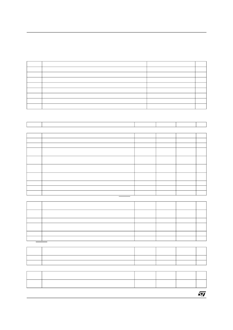
ELECTRICAL SPECIFICATIONS
Unless otherwise stated, electrical characteristics are specified over the operating range.
Typical values are given for V
BUS
= +5V, V
REGA
= 3.3V, V
REGD
= 3.3V, T
amb
= 25°C.
Absolute Maximum Rating
(AGND = DGND = USB GND = 0V, all voltages with respect to 0V)
Symbol
DV
DD
I
I
I
O
V
IA
V
ID
T
oper
T
stg
P
tot
Parameter
Value
-0.3, 6.0
-10, +10
-20, +20
-0.3, AV
DD
+ 0.3
-0.3, DV
DD
+ 0.3
0, +70
-55, +150
200
Unit
V
mA
mA
V
V
°C
°C
mW
Digital Power Supply
Input Current per Pin
Output Current per Pin
Analog Input Voltage
Digital Input Voltage
Operating Temperature
Storage Temperature
Maximum Power Dissipation
Warning : Operation beyond these limits may result in permanent damage to the device. Normal operation is not guaranted at these extremes.
Nominal DC Characteristics
(T
amb
= 0 to 70°C unless otherwise specified)
Symbol
POWER SUPPLY AND COMMON MODE VOLTAGE
V
BUS
Supply Voltage
I
VBUS
Supply Current
I
VBUSS
Supply Current in Suspend Mode (PSM = 1)
V
REGA
Analog regulated Output Power Supply (PSM =1)
Analog regulated Input Power Supply (PSM =0)
V
REGD
Digital regulated Output Power Supply (PSM =1)
Digital regulated Input Power Supply (PSM =0)
I
VREGA
Analog regulated Output Current (PSM =1)
Analog regulated Input Current (PSM =0)
I
VREGD
Digital regulated Output Current (PSM =1)
Digital regulated Input Current (PSM =0)
P
DLP
Low Power Mode (Suspend mode D2, wake-up on ring enabled)
P
D
Operating Power (SSI in power-down)
P
D
Operating Power (D0 power state)
DIGITAL INTERFACE (except XTALIN, XTALOUT, PSM and RESET) (these inputs have hysteresis)
V
IH
V
IL
Low Level Input Voltage
V
OH
V
OL
Low Level Output Voltage
I
LEAK
Input Leakage Current
I
OL
I
OH
Low Level Output Current (V
OHMin.
< V
OH
< V
REGD
)
V
HYST
Schmitt Trigger Hysteresis
C
IN
Input Capacitance
PSM, RESET (these inputs have hysteresis)
V
IH
V
IL
Low Level Input Voltage
I
LEAK
Input Leakage Current
V
HYST
Schmitt Trigger Hysteresis
CRYSTAL OSCILLATOR (XTALIN, XTALOUT)
V
IH
V
IL
Low Level Input Voltage
I
IH
I
IL
Low Level Input Current
Parameter
Min.
Typ.
Max.
Unit
4
5
5.25
V
TBD
TBD
3.4
3.3
3.4
3.3
mA
μ
A
V
V
V
V
mA
mA
mA
mA
mW
mW
mW
3.4-10%
3.3-10%
3.4-10%
3.3-10%
3.4+10%
3.3+10%
3.4+10%
3.3+10%
40
TBD
20
20
TBD
TBD
TBD
High Level Input Voltage
0.8 x V
REGD
0.2 x V
REGD
V
V
V
V
μ
A
mA
mA
V
pF
High Level Output Voltage
0.85 x V
REGD
0.4
±
1
2
High Level Output Current (0 < V
OL
< V
OLMax.
)
-2
0.8
3
High Level Input Voltage
0.7 x V
BUS
0.3 x V
BUS
±
1
V
V
μ
A
V
1
1.3
High Level Input Voltage
0.8 x V
REGA
0.2 x V
REGA
V
V
μ
A
μ
A
High Level Input Current
-20
20
ST7554
6/11
相關(guān)PDF資料 |
PDF描述 |
|---|---|
| ST7HUB | USB 1.1 HUB WITH 2 DOWNSTREAMS, FULL SPEED FUNCTION, 8-BIT MCU, 10-BIT ADC, 3 TIMERS, 2 PWMs |
| ST9293 | 48K ROM HCMOS MCUs WITH ON SCREEN DISPLAY AND A/D CONVERTER |
| ST9293J1 | 48K ROM HCMOS MCUs WITH ON SCREEN DISPLAY AND A/D CONVERTER |
| ST9294 | 24K ROM HCMOS MCU WITH ON SCREEN DISPLAY AND CLOSED-CAPTION DATA SLICER |
| ST95022 | 2 Kbit Serial SPI EEPROM with High Speed Clock |
相關(guān)代理商/技術(shù)參數(shù) |
參數(shù)描述 |
|---|---|
| ST7556 | 制造商:SITRONIX 制造商全稱:SITRONIX 功能描述:65 x 102 Dot Matrix LCD Controller/Driver |
| ST7558 | 制造商:SITRONIX 制造商全稱:SITRONIX 功能描述:65 x 102 Dot Matrix LCD Controller/Driver |
| ST755C | 制造商:未知廠家 制造商全稱:未知廠家 功能描述:ADJUSTABLE INVERTING NEGATIVE OUTPUT CURRENT MODE PWM REGULATORS |
| ST755CD | 功能描述:電流型 PWM 控制器 Adjust Sw Mode DC-DC RoHS:否 制造商:Texas Instruments 開關(guān)頻率:27 KHz 上升時(shí)間: 下降時(shí)間: 工作電源電壓:6 V to 15 V 工作電源電流:1.5 mA 輸出端數(shù)量:1 最大工作溫度:+ 105 C 安裝風(fēng)格:SMD/SMT 封裝 / 箱體:TSSOP-14 |
| ST755CDTR | 制造商:ST MICRO 功能描述:New |
發(fā)布緊急采購(gòu),3分鐘左右您將得到回復(fù)。