- 您現(xiàn)在的位置:買賣IC網(wǎng) > PDF目錄385872 > ST7554 (意法半導(dǎo)體) V.90 USB WORLD MODEM CONTROLLER PDF資料下載
參數(shù)資料
| 型號: | ST7554 |
| 廠商: | 意法半導(dǎo)體 |
| 英文描述: | V.90 USB WORLD MODEM CONTROLLER |
| 中文描述: | .90 USB世界調(diào)制解調(diào)器控制器 |
| 文件頁數(shù): | 4/11頁 |
| 文件大小: | 148K |
| 代理商: | ST7554 |
PIN DESCRIPTION
1 - Power Supply
(7 pins)
1.1 - Regulator Input Power Supply
(VBUS)
This pin must be connected to USB VBUS (+5V).
It supplies the integrated analog USB transceiver.
It is also the positive regulator power supply input
(5V) when ST7554 is in bus-powered mode
(PSM = 1) and it is used to internally generate the
3.3V supply for the digital and analog circuitry.
1.2 - Regulated Analog V
DD
Supply
(VREGA)
This pin is the analog power supply input (PSM = 0)
or analog 3.3V power supply output (PSM = 1).
This pin is the positive analog power supply for the
external Codec and DAA.
It is recommended to add a 1
μ
F capacitor between
VREGA and GNDA as close as possible to the
IC pins.
1.3 - Regulated V
DD
Supply
(VREGD)
This pin is the digital power supply input (PSM = 0)
or digital 3.3V power supply output (PSM = 1).
This pin is the positive digital power supply for the
external Codec and DAA.
It is recommended to add a 1
μ
F capacitor between
VREGA and GNDA as close as possible to the
IC pins.
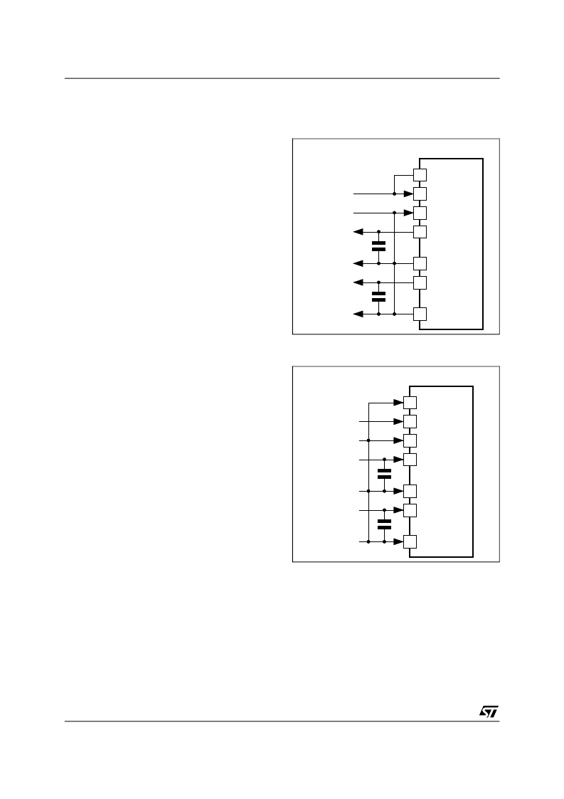
1.4 - Power Supply Mode
(PSM)
This pin controls the VREGD and VREGA power
supply mode.
When PSM = 1, the application is bus-powered.
The 3.3V power supply is generated internally from
VBUS. In this case VREGD and VREGA are out-
puts which can be used to supply 3.3V to external
devices (see Figure 1).
When PSM = 0, the application is self-powered.
VBUS must be still connected to the VBUS Pin of
the USB connector in order to supply the integrated
USB transceiver. Anyway in this case VREGD and
VREGA must be fed by a 3.3V externally regulated
digital and analog power supplies (see Figure 2).
1.5 - Ground
(DGND, AGND and GNDBUS)
DGND, AGND and GNDBUS are the digital, analog
and USB ground return pins respectively.
They should be connected together outside the
chip to the GND pin of the USB plug.
8 PSM
5 VBUS
3 GNDBUS
4 VREGD
32 DGND
6 VREGA
7 AGND
ST7554
from USB
to other
digital ICs
to other
analog ICs
7
Figure 1 :
ST7554 in Bus-Powered mode
(PSM = 1)
8 PSM
5 VBUS
3 GNDBUS
4 VREGD
32 DGND
6 VREGA
7 AGND
ST7554
from USB
from 3.3V
externally
regulated
supplies
7
Figure 2 :
ST7554 in Self Powered mode
(PSM = 0)
2 - USB Interface
(D+ , D-)
These pins are the positive and negative USB
differential data lines. They shall be both connected
to the USB plug or USB protection circuit via 27
series resistors for line impedance matching.
ST7554
4/11
相關(guān)PDF資料 |
PDF描述 |
|---|---|
| ST7554TQF7 | V.90 USB WORLD MODEM CONTROLLER |
| ST7HUB | USB 1.1 HUB WITH 2 DOWNSTREAMS, FULL SPEED FUNCTION, 8-BIT MCU, 10-BIT ADC, 3 TIMERS, 2 PWMs |
| ST9293 | 48K ROM HCMOS MCUs WITH ON SCREEN DISPLAY AND A/D CONVERTER |
| ST9293J1 | 48K ROM HCMOS MCUs WITH ON SCREEN DISPLAY AND A/D CONVERTER |
| ST9294 | 24K ROM HCMOS MCU WITH ON SCREEN DISPLAY AND CLOSED-CAPTION DATA SLICER |
相關(guān)代理商/技術(shù)參數(shù) |
參數(shù)描述 |
|---|---|
| ST7554TQF7 | 制造商:STMicroelectronics 功能描述:V.90 USB WORLD MODEM CONTROLLER - Bulk |
| ST7556 | 制造商:SITRONIX 制造商全稱:SITRONIX 功能描述:65 x 102 Dot Matrix LCD Controller/Driver |
| ST7558 | 制造商:SITRONIX 制造商全稱:SITRONIX 功能描述:65 x 102 Dot Matrix LCD Controller/Driver |
| ST755C | 制造商:未知廠家 制造商全稱:未知廠家 功能描述:ADJUSTABLE INVERTING NEGATIVE OUTPUT CURRENT MODE PWM REGULATORS |
| ST755CD | 功能描述:電流型 PWM 控制器 Adjust Sw Mode DC-DC RoHS:否 制造商:Texas Instruments 開關(guān)頻率:27 KHz 上升時間: 下降時間: 工作電源電壓:6 V to 15 V 工作電源電流:1.5 mA 輸出端數(shù)量:1 最大工作溫度:+ 105 C 安裝風(fēng)格:SMD/SMT 封裝 / 箱體:TSSOP-14 |
發(fā)布緊急采購,3分鐘左右您將得到回復(fù)。