- 您現(xiàn)在的位置:買賣IC網(wǎng) > PDF目錄385868 > ST330C16C3 (International Rectifier) PHASE CONTROL THYRISTORS PDF資料下載
參數(shù)資料
| 型號: | ST330C16C3 |
| 廠商: | International Rectifier |
| 英文描述: | PHASE CONTROL THYRISTORS |
| 中文描述: | 相位控制晶閘管 |
| 文件頁數(shù): | 6/8頁 |
| 文件大?。?/td> | 95K |
| 代理商: | ST330C16C3 |
ST330C..C Series
6
Bulletin I25155 rev. D 04/03
www.irf.com
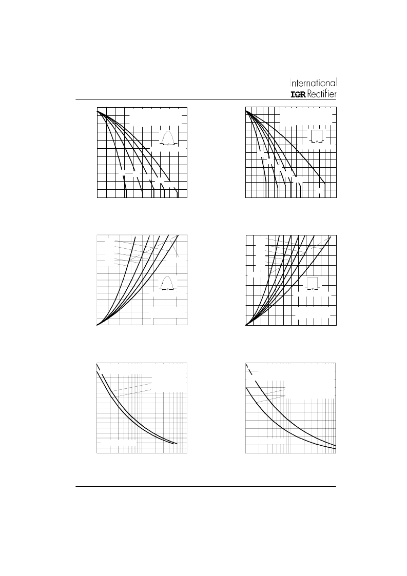
Fig. 3 - Current Ratings Characteristics
Fig. 4 - Current Ratings Characteristics
Fig. 5- On-state Power Loss Characteristics
Fig. 6- On-state Power Loss Characteristics
Fig. 7 - Maximum Non-Repetitive Surge Current
Single and Double Side Cooled
10
20
30
40
50
60
70
80
90
100
110
120
130
0
200 400 600 800 1000120014001600
DC
30°
60°
90°
120°
180°
Average On-state Current (A)
Conduction Period
M
ST330C..C Series
(Double Sde Cooled)
R (DC) = 0.04 K/W
20
30
40
50
60
70
80
90
100
110
120
130
0
200
400
600
800
1000
30°
60°
90°
120°
180°
Average On-state Current (A)
Conduction Angle
M
ST330C..C Series
(Double Sde Cooled)
R (DC) = 0.04 K/W
0
200
400
600
800
1000
1200
1400
1600
1800
0
200
400
600
800
1000 1200
DC
180°
120°
90°
60°
30°
RMSLimit
Conduction Period
M
Average On-state Current (A)
ST330C..C Series
T = 125°C
0
200
400
600
800
1000
1200
1400
0
100 200 300 400 500 600 700 800
180°
120°
90°
60°
30°
RMSLimit
Conduction Angle
M
Average On-state Current (A)
ST330C..C Series
T = 125°C
3500
4000
4500
5000
5500
6000
6500
7000
7500
8000
1
10
100
Number Of Equal Amplitude Half Cycle Current Pulses (N)
P
Initial T = 125°C
@60 Hz 0.0083 s
@50 Hz 0.0100 s
ST330C..C Series
At Any Rated Load Condition And With
Rated V Applied Following Surge.
3500
4000
4500
5000
5500
6000
6500
7000
7500
8000
8500
9000
0.01
0.1
1
Pulse Train Duration (s)
Versus Pulse Train Duration. Control
Of Conduction May Not Be Maintained.
P
Initial T = 125°C
No Voltage Reapplied
Rated V Reapplied
ST330C..C Series
Maximum Non Repetitive Surge Current
Fig. 8 - Maximum Non-Repetitive Surge Current
Single and Double Side Cooled
相關(guān)PDF資料 |
PDF描述 |
|---|---|
| ST330C16C3L | PHASE CONTROL THYRISTORS |
| ST330C04C0L | PHASE CONTROL THYRISTORS |
| ST330C04C0 | PHASE CONTROL THYRISTORS |
| ST330C04C1 | PHASE CONTROL THYRISTORS |
| ST330C04C2 | PHASE CONTROL THYRISTORS |
相關(guān)代理商/技術(shù)參數(shù) |
參數(shù)描述 |
|---|---|
| ST330C16C3L | 制造商:IRF 制造商全稱:International Rectifier 功能描述:PHASE CONTROL THYRISTORS |
| ST330C16C3LPBF | 制造商:VISHAY 制造商全稱:Vishay Siliconix 功能描述:Phase Control Thyristors (Hockey PUK Version), 720 A |
| ST330C16C3PBF | 制造商:VISHAY 制造商全稱:Vishay Siliconix 功能描述:Phase Control Thyristors (Hockey PUK Version), 720 A |
| ST330C16CO | 制造商:n/a 功能描述:_ |
| ST330C16L | 制造商:International Rectifier 功能描述: |
發(fā)布緊急采購,3分鐘左右您將得到回復(fù)。