- 您現(xiàn)在的位置:買賣IC網(wǎng) > PDF目錄372295 > ST24FW21B1TR (意法半導體) 1 Kbit x8 Dual Mode Serial EEPROM for VESA PLUG & PLAY PDF資料下載
參數(shù)資料
| 型號: | ST24FW21B1TR |
| 廠商: | 意法半導體 |
| 英文描述: | 1 Kbit x8 Dual Mode Serial EEPROM for VESA PLUG & PLAY |
| 中文描述: | 1千位x8雙模式串行EEPROM的韋莎插頭 |
| 文件頁數(shù): | 10/22頁 |
| 文件大小: | 159K |
| 代理商: | ST24FW21B1TR |

Symbol
Alt
Parameter
Min
Max
Unit
t
CH1CH2 (1)
t
R
Clock Rise Time
300
ns
t
CL1CL2 (1)
t
F
Clock Fall Time
300
ns
t
DH1DH2
(1)
t
R
SDA Rise Time
20
300
ns
t
DL1DL2(1)
t
F
SDA Fall Time
20
300
ns
t
CHDX(2)
t
SU:STA
Clock High to Input Transition
600
ns
t
CHCL
t
HIGH
Clock Pulse Width High
600
ns
t
DLCL
t
HD:STA
Input Low to Clock Low (START)
600
ns
t
CLDX
t
HD:DAT
Clock Low to Input Transition
0
μ
s
t
CLCH
t
LOW
Clock Pulse Width Low
1.3
μ
s
t
DXCX
t
SU:DAT
Input Transition to Clock Transition
100
ns
t
CHDH
t
SU:STO
Clock High to Input High (STOP)
600
ns
t
DHDL
t
BUF
Input High to Input Low (Bus Free)
1.3
μ
s
t
CLQV
t
AA
Clock Low to Data Out Valid
200
900
ns
t
CLQX
t
DH
Clock Low to Data Out Transition
200
ns
f
C
f
SCL
Clock Frequency
400
kHz
t
W
t
WR
Write Time
10
ms
Notes:
1. Sampled only, not 100% tested.
2. For a reSTART condition, or following a write cycle.
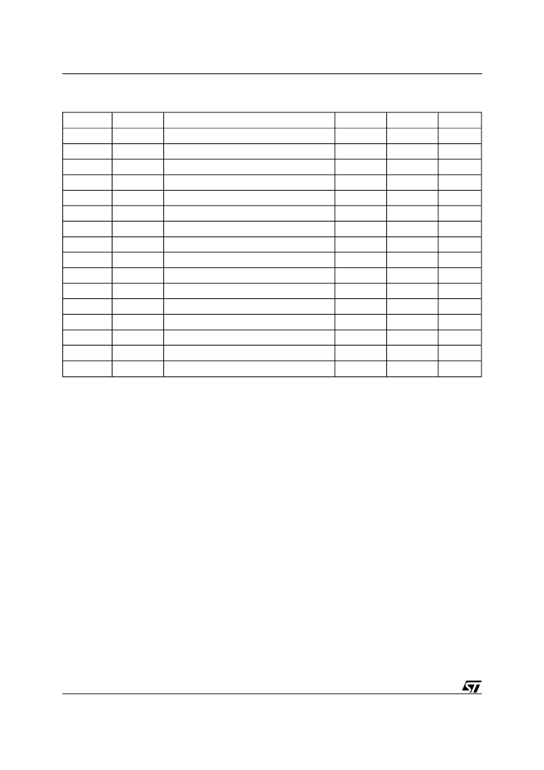
Table 7. AC Characteristics, I
2
C Bidirectional Mode for Clock Frequency = 400kHz
(T
A
= –40 to 85
°
C; V
CC
= 3.6 to 5.5V or V
CC
= 2.5 to 5.5V)
I
2
C Bus Background
The ST24xy21 supports the I
2
C protocol. This pro-
tocol defines any device that sends data onto the
bus as a transmitter and any device that reads the
data as a receiver. The device that controls the data
transfer is known as the master and the other as
the slave. The master will always initiate a data
transfer and will provide the serial clock for syn-
chronisation. The ST24xy21 are always slave de-
vices in all communications.
Start Condition.
START is identified by a high to
low transition of the SDA line while the clock SCL
is stable in the high state. A START condition must
precede any command for data transfer. Except
during a programming cycle, the ST24xy21 con-
tinuously monitor the SDA and SCL signals for a
START condition and will not respond unless one
is given.
The ST24LC21B, ST24LW21, ST24FC21 and
ST24FW21 are not executing a START condition if
this START condition happens at any time inside a
byte. The ST24FC21B executes a START condi-
tion when this START condition happens at any
time inside a byte.
Stop Condition.
STOP is identified by a low to high
transition of the SDA line while the clock SCL is
stable in the high state. A STOP condition termi-
nates communication between the ST24xy21 and
the bus master. A STOP condition at the end of a
Read command (after the No ACK) forces the
standby state. A STOP condition at the end of a
Write command triggers the internal EEPROM
write cycle.
The ST24LC21B, ST24LW21, ST24FC21 and
ST24FW21 are not executing a STOP condition if
this STOP condition happens at any time inside a
byte. The ST24FC21B executes a STOP condition
when this STOP condition happens at any time
inside a byte.
Acknowledge Bit (ACK).
An acknowledge signal
is used to indicate a successfull data transfer. The
bus transmitter, either master or slave, will release
the SDA bus after sending 8 bits of data. During the
9th clock pulse period the receiver pulls the SDA
bus low to acknowledge the receipt of the 8 bits of
data.
Data Input.
During data input, the ST24xy21 sam-
ple the SDA bus signal on the rising edge of the
clock SCL. Note that for correct device operation
10/22
ST24LC21B, ST24LW21, ST24FC21, ST24FC21B, ST24FW21
相關PDF資料 |
PDF描述 |
|---|---|
| ST24FW21M1TR | 1 Kbit x8 Dual Mode Serial EEPROM for VESA PLUG & PLAY |
| ST24FW21M6TR | 1 Kbit x8 Dual Mode Serial EEPROM for VESA PLUG & PLAY |
| ST24LW21B1TR | 1 Kbit x8 Dual Mode Serial EEPROM for VESA PLUG & PLAY |
| ST24LW21M1TR | 1 Kbit x8 Dual Mode Serial EEPROM for VESA PLUG & PLAY |
| ST24LW21M6TR | 1 Kbit x8 Dual Mode Serial EEPROM for VESA PLUG & PLAY |
相關代理商/技術參數(shù) |
參數(shù)描述 |
|---|---|
| ST24FW21B6 | 功能描述:電可擦除可編程只讀存儲器 Dual Mode 1K (128x8) RoHS:否 制造商:Atmel 存儲容量:2 Kbit 組織:256 B x 8 數(shù)據(jù)保留:100 yr 最大時鐘頻率:1000 KHz 最大工作電流:6 uA 工作電源電壓:1.7 V to 5.5 V 最大工作溫度:+ 85 C 安裝風格:SMD/SMT 封裝 / 箱體:SOIC-8 |
| ST24FW21B6TR | 制造商:STMICROELECTRONICS 制造商全稱:STMicroelectronics 功能描述:1 Kbit x8 Dual Mode Serial EEPROM for VESA PLUG & PLAY |
| ST24FW21M1 | 制造商:未知廠家 制造商全稱:未知廠家 功能描述:I2C Serial EEPROM |
| ST24FW21M1TR | 制造商:STMICROELECTRONICS 制造商全稱:STMicroelectronics 功能描述:1 Kbit x8 Dual Mode Serial EEPROM for VESA PLUG & PLAY |
| ST24FW21M6 | 制造商:未知廠家 制造商全稱:未知廠家 功能描述:I2C Serial EEPROM |
發(fā)布緊急采購,3分鐘左右您將得到回復。