- 您現(xiàn)在的位置:買賣IC網(wǎng) > PDF目錄376378 > SMCG5.0C (MICROSEMI CORP-SCOTTSDALE) SURFACE MOUNT 1500 Watt Transient Voltage Suppressor PDF資料下載
參數(shù)資料
| 型號: | SMCG5.0C |
| 廠商: | MICROSEMI CORP-SCOTTSDALE |
| 元件分類: | 參考電壓二極管 |
| 英文描述: | SURFACE MOUNT 1500 Watt Transient Voltage Suppressor |
| 中文描述: | 1500 W, BIDIRECTIONAL, SILICON, TVS DIODE, DO-215AB |
| 封裝: | PLASTIC PACKAGE-2 |
| 文件頁數(shù): | 1/4頁 |
| 文件大小: | 584K |
| 代理商: | SMCG5.0C |
SURFACE MOUNT 1500 Watt
Transient Voltage Suppressor
Microsemi
Scottsdale Division
8700 E. Thomas Rd. PO Box 1390, Scottsdale, AZ 85252 USA, (480) 941-6300, Fax: (480) 947-1503
Page 1
Copyright
2005
2-23-05 REV C
W
M
.
C
SCOTTSDALE DIVISION
SMCJ5.0 thru SMCJ170CA
and SMCG5.0 thru SMCG170CA
S
DESCRIPTION
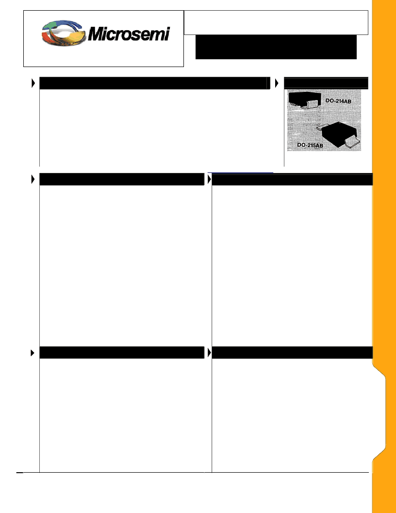
APPEARANCE
The SMCJ5.0-170A or SMCG5.0-170A series of 1500 W Transient Voltage
Suppressors (TVSs) protects a variety of voltage-sensitive components from
destruction or degradation. It is available in J-bend design (SMCJ) with the
DO-214AB package for greater PC board mounting density or in a Gull-wing
design (SMCG) in the DO-215AB for visible solder connections. Selections
include unidirectional and bidirectional. They can protect from secondary
lightning effects per IEC61000-4-5 and class levels defined herein, or for
inductive switching environments and induced RF protection. Since their
response time is virtually instantaneous, they can also be used in protection
from ESD and EFT per IEC61000-4-2 and IEC61000-4-4.
IMPORTANT:
For the most current data, consult
MICROSEMI’s
website:
FEATURES Economical surface mount design in both J-bend or
Gull-wing terminations
Available in both Unidirectional and Bidirectional
construction with a C or CA suffix
Suppresses transients up to 1500 watts @ 10/1000 μs
Qualified to UL497B
Optional 100%
screening for avionics grade
is
available by adding MA prefix to part number for added
100% temperature cycle -55
C to +125
C (10X) as well
as surge (3X) and 24 hours HTRB with post test V
Z
&
I
R
(in the operating direction for unidirectional or both
directions for bidirectional)
Options for screening in accordance with MIL-PRF-
19500 for JAN, JANTX, JANTXV, and JANS are
available by adding MQ, MX, MV, or MSP prefixes
respectively to part numbers.
Axial-lead equivalent packages for thru-hole mounting
available as 1.5KE6.8 to 1.5KE200CA or 1N6267 thru
1N6303A and 1N5908 (consult factory for other
surface mount options)
Moisture classification is Level 1 with no dry pack
required per IPC/JEDEC J-STD-020B
MAXIMUM RATINGS
Peak Pulse Power dissipation at 25
o
C: 1500 watts at
10/1000
μ
s (also see Fig 1,2, and 3)
Impulse repetition rate (duty factor): 0.01%
t
clamping
(0 volts to V
(BR)
min.): < 100 ps theoretical for
unidirectional and < 5 ns for bidirectional
Operating and Storage temperature: -65
o
C to +150
o
C
Thermal resistance: 20
o
C/W junction to lead, or 80
o
C/W
junction to ambient when mounted on FR4 PC board
(1oz Cu) with recommended footprint (see last page)
Steady-State Power dissipation: 6 watts at T
L
= 30
o
C,
or 1.56 watts at T
A
= 25
C when mounted on FR4 PC
board with recommended footprint
Forward Surge: 200 Amps peak impulse of 8.3 ms
half-sine wave at 25oC (unidirectional only)
Solder temperatures: 260
o
C for 10 s (maximum)
NOTE: All SMC series are
equivalent to prior SMM package
identifications.
APPLICATIONS / BENEFITS
Selections for 5.0 to 170 volts standoff voltages (V
WM
)
Protection from switching transients and induced RF
Protection from ESD, and EFT per IEC 61000-4-2 and
IEC 61000-4-4
Secondary lightning protection per IEC61000-4-5 with
42 Ohms source impedance:
Class 1: SMC 5.0 to SMC 170A or CA
Class 2: SMC 5.0 to SMC 150A or CA
Class 3: SMC 5.0 to SMC 75A or CA
Class 4: SMC 5.0 to SMC 36A or CA
Secondary lightning protection per IEC61000-4-5 with
12 Ohms source impedance:
Class 1 : SMC 5.0 to SMC 90A or CA
Class 2: SMC 5.0 to SMC 45A or CA
Class 3: SMC 5.0 to SMC 24A or CA
Class 4: SMC 5.0 to SMC 11A or CA
Secondary lightning protection per IEC61000-4-5 with
2 Ohms source impedance:
Class 2: SMC 5.0 to SMC 22A or CA
Class 3: SMC 5.0 to SMC 10A or CA
MECHANICAL AND PACKAGING
CASE: Void-free transfer molded thermosetting
epoxy body meeting UL94V-0
TERMINALS: Gull-wing or C-bend (modified J-bend)
leads, tin-lead plated solderable to MIL-STD-750,
method 2026
POLARITY: Cathode indicated by band. No marking
on bi-directional devices
MARKING: Part number without SM prefix (e.g.
C5.0, C5.0A, C5.0CA, C36, C36A, C36CA, etc.)
TAPE & REEL option: Standard per EIA-481-2 with
16 mm tape, 750 per 7 inch reel or 2500 per 13 inch
reel (add “TR” suffix to part number)
WEIGHT
: 0.25 grams
相關(guān)PDF資料 |
PDF描述 |
|---|---|
| SMCG7.0C | SURFACE MOUNT 1500 Watt Transient Voltage Suppressor |
| SMCG7.0CA | SURFACE MOUNT 1500 Watt Transient Voltage Suppressor |
| SMCG7.5C | SURFACE MOUNT 1500 Watt Transient Voltage Suppressor |
| SMCG7.5CA | SURFACE MOUNT 1500 Watt Transient Voltage Suppressor |
| SMCG9.0C | SURFACE MOUNT 1500 Watt Transient Voltage Suppressor |
相關(guān)代理商/技術(shù)參數(shù) |
參數(shù)描述 |
|---|---|
| SMCG51 | 制造商:MICROSEMI 制造商全稱:Microsemi Corporation 功能描述:UNIDIRECTIONAL AND BIDIRECTIONAL SURFACE MOUNT |
| SMCG51A | 制造商:MICROSEMI 制造商全稱:Microsemi Corporation 功能描述:UNIDIRECTIONAL AND BIDIRECTIONAL SURFACE MOUNT |
| SMCG51A/1 | 制造商:Vishay Intertechnologies 功能描述:Diode TVS Single Uni-Dir 51V 1.5KW 2-Pin SMCG Bulk |
| SMCG51A/57T | 功能描述:TVS 二極管 - 瞬態(tài)電壓抑制器 1500W 51V Unidirect RoHS:否 制造商:Vishay Semiconductors 極性:Bidirectional 工作電壓: 擊穿電壓:58.9 V 鉗位電壓:77.4 V 峰值浪涌電流:38.8 A 系列: 封裝 / 箱體:DO-214AB 最小工作溫度:- 55 C 最大工作溫度:+ 150 C |
| SMCG51A/59T | 功能描述:TVS 二極管 - 瞬態(tài)電壓抑制器 1500W 51V Unidirect RoHS:否 制造商:Vishay Semiconductors 極性:Bidirectional 工作電壓: 擊穿電壓:58.9 V 鉗位電壓:77.4 V 峰值浪涌電流:38.8 A 系列: 封裝 / 箱體:DO-214AB 最小工作溫度:- 55 C 最大工作溫度:+ 150 C |
發(fā)布緊急采購,3分鐘左右您將得到回復(fù)。