- 您現(xiàn)在的位置:買賣IC網(wǎng) > PDF目錄378699 > SM8222BS (Seiko NPC Corporation) Caller ID Service IC with Call Waiting PDF資料下載
參數(shù)資料
| 型號: | SM8222BS |
| 廠商: | Seiko NPC Corporation |
| 英文描述: | Caller ID Service IC with Call Waiting |
| 中文描述: | 來電顯示服務(wù)集成電路呼叫等待 |
| 文件頁數(shù): | 15/15頁 |
| 文件大?。?/td> | 112K |
| 代理商: | SM8222BS |
pemnr
SM8222A/B
NIPPON PRECISION CIRCUITS—15
NIPPON PRECISION CIRCUITS INC. reserves the right to make changes to the products described in this data sheet in order to
improve the design or performance and to supply the best possible products. Nippon Precision Circuits Inc. assumes no responsibility for
the use of any circuits shown in this data sheet, conveys no license under any patent or other rights, and makes no claimthat the circuits
are free frompatent infringement. Applications for any devices shown in this data sheet are for illustration only and Nippon Precision
Circuits Inc. makes no claimor warranty that such applications will be suitable for the use specified without further testing or modification.
The products described in this data sheet are not intended to use for the apparatus which influence human lives due to the failure or
malfunction of the products. Customers are requested to comply with applicable laws and regulations in effect now and hereinafter,
including compliance with export controls on the distribution or dissemnation of the products. Customers shall not export, directly or
indirectly, any products without first obtaining required licenses and approvals fromappropriate government agencies.
NIPPON PRECISION CIRCUITS INC.
4-3, Fukuzum 2-chome
Koto-ku, Tokyo 135-8430, Japan
Telephone: 03-3642-6661
Facsimle: 03-3642-6698
NC9811BE
1999.1
NIPPON PRECISION CIRCUITS INC.
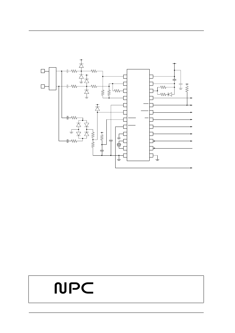
TYPICAL APPLICATION CIRCUIT
All circuit component values are shown for reference only. These values are not guaranteed for mass production specification.
RING
TIP
GS
DOUT
DCLK
CAP
STGT
STD
EST
MODE
FSKEN
AGND
OSCIN
OSCOUT
RDIN
GND
VDD
PDWN
IC
RDRC
RDET
INT
CDET
DR
100k
20%
0.1
μ
F
20%
VDD
100nF
20%
220nF
20%
150k
5%
VDD
53.6k
1%
VDD
301k
5%
464k
1%
60.4k
1%
VDD
34k
1%
VDD
200k
5%
499k
5%
499k
5%
(240k)
1%
22nF
5%
22nF
5%
100nF
5%
100nF
5%
L1
L2
34k
1%
Protection
430K
(240k)
1%
( ) = when SM8222B
相關(guān)PDF資料 |
PDF描述 |
|---|---|
| SM8223A | FSK Decoder and DTMF Receiver IC |
| SM8224 | Dual-Tone Receiver IC |
| SM8224B | Dual-Tone Receiver IC |
| SM8224BM | Dual-Tone Receiver IC |
| SM8224BS | Dual-Tone Receiver IC |
相關(guān)代理商/技術(shù)參數(shù) |
參數(shù)描述 |
|---|---|
| SM8223A | 制造商:NPC 制造商全稱:Nippon Precision Circuits Inc 功能描述:FSK Decoder and DTMF Receiver IC |
| SM8224 | 制造商:NPC 制造商全稱:Nippon Precision Circuits Inc 功能描述:Dual-Tone Receiver IC |
| SM8224B | 制造商:NPC 制造商全稱:Nippon Precision Circuits Inc 功能描述:Dual-Tone Receiver IC |
| SM8224BM | 制造商:NPC 制造商全稱:Nippon Precision Circuits Inc 功能描述:Dual-Tone Receiver IC |
| SM8224BS | 制造商:NPC 制造商全稱:Nippon Precision Circuits Inc 功能描述:Dual-Tone Receiver IC |
發(fā)布緊急采購,3分鐘左右您將得到回復(fù)。