- 您現(xiàn)在的位置:買賣IC網(wǎng) > PDF目錄368672 > SE370C777AFZT 8-BIT MICROCONTROLLER PDF資料下載
參數(shù)資料
| 型號: | SE370C777AFZT |
| 元件分類: | 8位微控制器 |
| 英文描述: | 8-BIT MICROCONTROLLER |
| 中文描述: | 8位微控制器 |
| 文件頁數(shù): | 6/48頁 |
| 文件大小: | 711K |
| 代理商: | SE370C777AFZT |
第1頁第2頁第3頁第4頁第5頁當(dāng)前第6頁第7頁第8頁第9頁第10頁第11頁第12頁第13頁第14頁第15頁第16頁第17頁第18頁第19頁第20頁第21頁第22頁第23頁第24頁第25頁第26頁第27頁第28頁第29頁第30頁第31頁第32頁第33頁第34頁第35頁第36頁第37頁第38頁第39頁第40頁第41頁第42頁第43頁第44頁第45頁第46頁第47頁第48頁
TMS370Cx36
8-BIT MICROCONTROLLER
SPNS039B – JANUARY 1996 – REVISED FEBRUARY 1997
6
POST OFFICE BOX 1443
HOUSTON, TEXAS 77251–1443
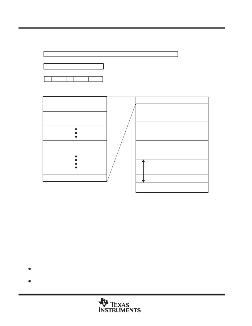
central processing unit (CPU) (continued)
Figure 1 Illustrates the CPU registers and memory blocks.
Reserved
Peripheral File
01FFh
0200h
02FFh
0300h
0FFFh
1000h
10BFh
10C0h
1EFFh
1F00h
3FFFh
4000h
Interrupts and Reset Vectors;
Trap Vectors
Reserved
7FFFh
8000h
0
RAM (Includes up to 256-Byte Registers File)
0
15
Program Counter
7
Legend:
C=Carry
N=Negative
Z=Zero
V=Overflow
IE2=Level 2 interrupts Enable
IE1=Level 1 interrupts Enable
IE1
2
IE2
3
Z
5
N
6
C
7
0
1
4
V
Status Register (ST)
Stack Pointer (SP)
R0(A)
R1(B)
R3
R127
0000h
0001h
0002h
007Fh
R255
0003h
R2
00FFh
256-Byte Standby RAM
1FFFh
2000h
7F9Ch
7F9Bh
256-Byte RAM
00FFh
0100h
017Fh
0180h
128-Byte PACT Dual-Port RAM
0000h
Reserved
256-Byte Data EEPROM
Reserved
16K-Byte ROM/EPROM
Reserved
FFFFh
Reserved means the address space is reserved for future expansion.
Figure 1. Programmer’s Model
stack pointer (SP)
The SP is an 8-bit CPU register. Stack operates as a last-in, first-out, read/write memory. Typically, the stack
is used to store the return address on subroutine calls as well as the ST contents during interrupt sequences.
The SP points to the last entry or top of the stack. The SP is incremented automatically before data is pushed
onto the stack and decremented after data is popped from the stack. The stack can be placed anywhere in the
on-chip RAM.
status register (ST)
The ST monitors the operation of the instructions and contains the global interrupt-enable bits. The ST includes
four status bits (condition flags) and two interrupt-enable bits.
The four status bits indicate the outcome of the previous instruction; conditional instructions (for example,
the conditional-jump instructions) use the status bits to determine program flow.
The two interrupt-enable bits control the two interrupt levels.
相關(guān)PDF資料 |
PDF描述 |
|---|---|
| SE370C777AJNT | 8-BIT MICROCONTROLLER |
| SE370C6C2AJDT | 8-BIT MICROCONTROLLER |
| SE370C710FZS | 8-BIT MICROCONTROLLER |
| SE370C712AJDT | 8-BIT MICROCONTROLLER |
| SE370C712BFZT | 8-BIT MICROCONTROLLER |
相關(guān)代理商/技術(shù)參數(shù) |
參數(shù)描述 |
|---|---|
| SE370C777AJNT | 制造商:未知廠家 制造商全稱:未知廠家 功能描述:8-Bit Microcontroller |
| SE370C777AYYZ | 制造商:TI 制造商全稱:Texas Instruments 功能描述:TMS370 MICROCONTROLLER FAMILY DATA BOOK |
| SE370C792 | 制造商:TI 制造商全稱:Texas Instruments 功能描述:8-BIT MICROCONTROLLER |
| SE370C792YYZ | 制造商:TI 制造商全稱:Texas Instruments 功能描述:TMS370 MICROCONTROLLER FAMILY DATA BOOK |
| SE3806 | 制造商:SEAWARD 制造商全稱:SEAWARD 功能描述:1.25MHz, 600mA Synchronous Step-Down Regulator |
發(fā)布緊急采購,3分鐘左右您將得到回復(fù)。