- 您現(xiàn)在的位置:買賣IC網(wǎng) > PDF目錄192734 > SD-14621DS-204Y (DATA DEVICE CORP) SYNCHRO OR RESOLVER TO DIGITAL CONVERTER, CQIP54 PDF資料下載
參數(shù)資料
| 型號: | SD-14621DS-204Y |
| 廠商: | DATA DEVICE CORP |
| 元件分類: | 位置變換器 |
| 英文描述: | SYNCHRO OR RESOLVER TO DIGITAL CONVERTER, CQIP54 |
| 封裝: | 1.500 X 0.780 INCH, 0.210 INCH HEIGHT, HERMETIC SEALED, CERAMIC, DIP-54 |
| 文件頁數(shù): | 8/12頁 |
| 文件大小: | 150K |
| 代理商: | SD-14621DS-204Y |
5
Data Device Corporation
www.ddc-web.com
SD-14620
J-04/03-0
RESOLUTION
B
A
10 bit
0
12 bit
0
1
14 bit
1
0
16 bit
1
THEORY OF OPERATION
The SD-14620 Series of converters are based upon a single chip
CMOS custom monolithic. Using the latest technology, precision
analog circuitry is merged with digital logic to form a complete,
high-performance tracking Synchro/Resolver-to-Digital (S/D,
R/D) converter.
CONVERTER OPERATION
FIGURE 1 is the Functional Block Diagram of the SD-14620
Series. The converter operates with a single +5 VDC power sup-
ply and each channel internally generates a negative voltage of
approximately 5 volts. These negative voltages are connected to
pin 52 (channel “A” filter point) and pin 24 (channel “B” filter
point) — see GENERAL SETUP CONSIDERATIONS.
The converter is made up of three main sections; an input front-
end, an error processor, and a digital interface. The converter
front-end differs for synchro, resolver and direct inputs. An elec-
tronic Scott-T is used for synchro inputs, a resolver conditioner
for resolver inputs, and a sine and cosine voltage follower for
direct inputs. These amplifiers feed the high accuracy Control
Transformer (CT). Its other input is the 16-bit digital angle
φ. Its
output is an analog error angle, or difference angle, between the
two inputs. The CT performs the ratiometric trigonometric com-
putation of SIN
θCOSφ - COSθSINφ = SIN(θ - φ) using amplifiers,
switches, logic, and capacitors in precision ratios. The converter
accuracy is limited by the precision of the computing elements in
the CT. For enhanced accuracy, the CT in these converters use
capacitors in precision ratios, instead of the more conventional
precision resistor ratios. Capacitors that are used as computing
elements with op-amps are sampled at a high rate to eliminate
drift and the op-amp offsets.
The error processing is performed using the industry standard
technique for type II tracking R/D converters. The DC error is
integrated yielding a velocity voltage which in turn drives a volt-
age- controlled oscillator (VCO). This VCO is an incremental inte-
grator (constant-voltage input to position-rate output) that,
together with the velocity integrator, forms a type II servo feed-
back loop. A lead in the frequency response is introduced to sta-
bilize the loop and a lag at a higher frequency is introduced to
reduce the gain and ripple at the carrier frequency and above.
GENERAL SET-UP CONSIDERATIONS
The following recommendations should be considered when
connecting the SD-14620 Series converters:
1) The +5 VDC power supply input is on pin 18. For performance
with the lowest amount of noise it is recommended that a
10 F/10 VDC (or larger) tantalum filter capacitor be connect-
ed to ground (pin 19) near the converter package.
2) Direct inputs are referenced to Analog Ground (A GND).
Connections should be made as close to the converter pack-
age as possible to minimize noise. Channel A should be ref-
erenced to A GND-A (pin 5) and Channel B should be refer-
enced to A GND-B (pin 32).
3) A 47 F/10 V tantalum filter capacitor must be added exter-
nally from pin 52 (channel “A” filter point) to pin 19 (ground). In
addition, a 47 F/10 Vdc tantalum filter capacitor must be
added externally from pin 24 (channel “B” filter point) to pin 19
(ground).
SPECIAL FUNCTIONS
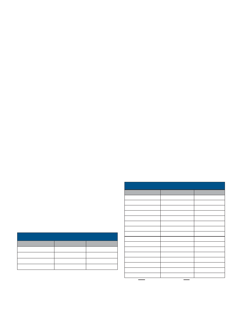
PROGRAMMABLE RESOLUTION
Resolution is controlled by pins 49 and 50 for channel A; pins 21
and 22 for channel B. The resolution can be changed during con-
verter operation, so the appropriate resolution and velocity
dynamics can be changed as needed. To insure that a race con-
dition does not exist between counting and changing the resolu-
tion, the resolution control is latched internally. Refer to TABLE 2
for Channel A and B resolution control.
Note: HBE enables the MSB byte and LBE enables the LSB byte.
10800
180
1 (MSB ALL MODES)
MIN/BIT
DEG/BIT
BIT
TABLE 3. DIGITAL ANGLE OUTPUTS
TABLE 2. RESOLUTION CONTROL (A AND B)
5400
90
2
2700
45
3
1350
22.5
4
675
11.25
5
337.5
5.625
6
168.75
2.813
7
84.38
1.406
8
42.19
0.7031
9
21.09
0.3516
10 (LSB 10-BIT MODE)
10.55
0.1758
11
5.27
0.0879
12 (LSB 12-BIT MODE)
2.64
0.0439
13
1.32
0.0220
14 (LSB 14-BIT MODE)
0.66
0.0110
15
0.33
0.0055
16 (LSB 16-BIT MODE)
相關(guān)PDF資料 |
PDF描述 |
|---|---|
| SD-14621DS-204Z | SYNCHRO OR RESOLVER TO DIGITAL CONVERTER, CQIP54 |
| SD-14621DS-205Q | SYNCHRO OR RESOLVER TO DIGITAL CONVERTER, CQIP54 |
| SD-14621DS-205W | SYNCHRO OR RESOLVER TO DIGITAL CONVERTER, CQIP54 |
| SD-14621DS-222L | SYNCHRO OR RESOLVER TO DIGITAL CONVERTER, CQIP54 |
| SD-14621DS-222S | SYNCHRO OR RESOLVER TO DIGITAL CONVERTER, CQIP54 |
相關(guān)代理商/技術(shù)參數(shù) |
參數(shù)描述 |
|---|---|
| SD-14621FS-295 | 制造商:DDC 功能描述: |
| SD1463 | 制造商:STMICROELECTRONICS 制造商全稱:STMicroelectronics 功能描述:RF & MICROWAVE TRANSISTORS VHF/UHF APPLICATIONS |
| SD1468 | 制造商:MICROSEMI 制造商全稱:Microsemi Corporation 功能描述:RF AND MICROWAVE TRANSISTORS WIDEBAND VHF-UHF CLASS C |
| SD14-680 | 制造商:COOPER BUSSMANN 功能描述:Inductor Power Shielded Wirewound 68uH 20% 100KHz Ferrite 474mA 1.11Ohm DCR 2020 T/R 制造商:COOPER BUSSMANN 功能描述:Ind Power Shielded Wirewound 68uH 20% 100KHz Ferrite 474mA 2020 T/R |
| SD14-680-R | 功能描述:固定電感器 68uH 0.449A 1.11ohms RoHS:否 制造商:AVX 電感:10 uH 容差:20 % 最大直流電流:1 A 最大直流電阻:0.075 Ohms 工作溫度范圍:- 40 C to + 85 C 自諧振頻率:38 MHz Q 最小值:40 尺寸:4.45 mm W x 6.6 mm L x 2.92 mm H 屏蔽:Shielded 端接類型:SMD/SMT 封裝 / 箱體:6.6 mm x 4.45 mm |
發(fā)布緊急采購,3分鐘左右您將得到回復(fù)。