- 您現(xiàn)在的位置:買賣IC網(wǎng) > PDF目錄379352 > SC16C750BIA44 (NXP Semiconductors N.V.) 5 V, 3.3 V and 2.5 V UART with 64-byte FIFOs PDF資料下載
參數(shù)資料
| 型號: | SC16C750BIA44 |
| 廠商: | NXP Semiconductors N.V. |
| 元件分類: | 收發(fā)器 |
| 英文描述: | 5 V, 3.3 V and 2.5 V UART with 64-byte FIFOs |
| 封裝: | SC16C750BIA44<SOT187-2 (PLCC44)|<<http://www.nxp.com/packages/SOT187-2.html<1<week 41, 2004,;SC16C750BIA44<SOT187-2 (PLCC44)|<<http://www.nxp.com/packages/SOT187-2.html&l |
| 文件頁數(shù): | 23/44頁 |
| 文件大?。?/td> | 212K |
| 代理商: | SC16C750BIA44 |
第1頁第2頁第3頁第4頁第5頁第6頁第7頁第8頁第9頁第10頁第11頁第12頁第13頁第14頁第15頁第16頁第17頁第18頁第19頁第20頁第21頁第22頁當(dāng)前第23頁第24頁第25頁第26頁第27頁第28頁第29頁第30頁第31頁第32頁第33頁第34頁第35頁第36頁第37頁第38頁第39頁第40頁第41頁第42頁第43頁第44頁
SC16C750B_5
NXP B.V. 2008. All rights reserved.
Product data sheet
Rev. 05 — 17 October 2008
23 of 44
NXP Semiconductors
SC16C750B
5 V, 3.3 V and 2.5 V UART with 64-byte FIFOs
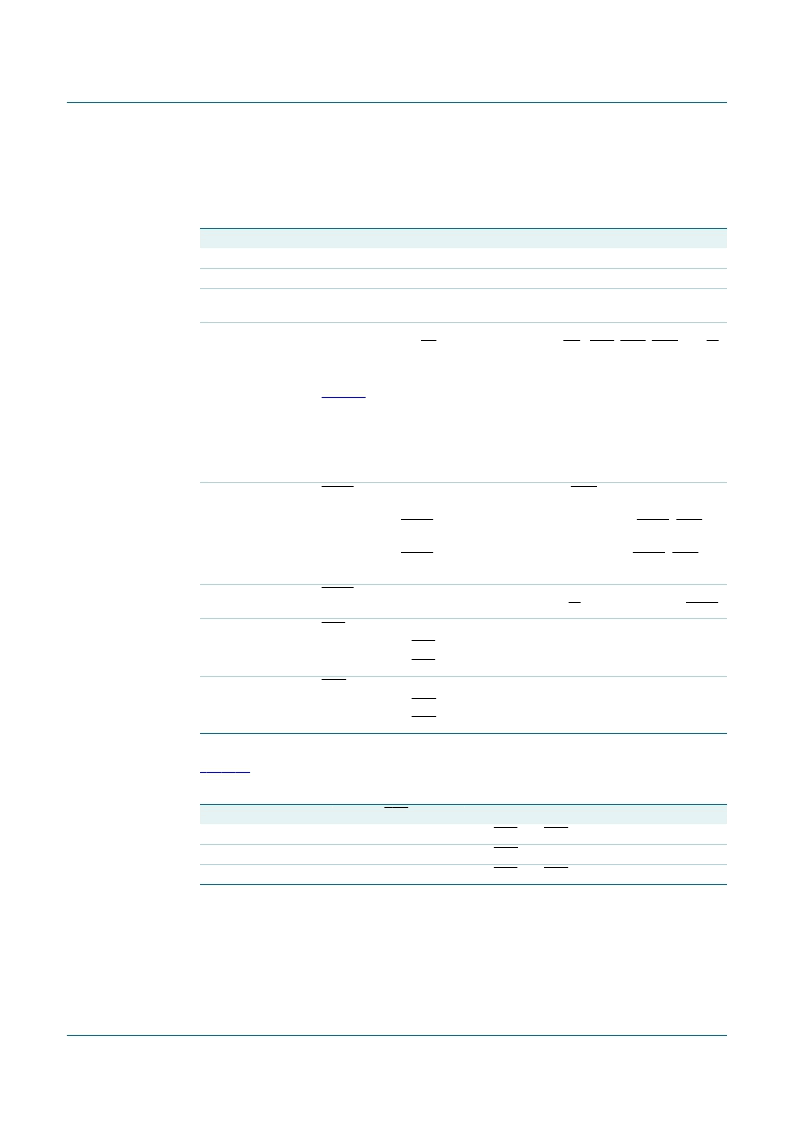
7.6 Modem Control Register (MCR)
This register controls the interface with the modem or a peripheral device.
The flow control can be configured by programming MCR[1] and MCR[5] as shown in
Table 19
.
Table 18.
Bit
7
6
5
Modem Control Register bits description
Symbol
Description
MCR[7]
reserved; set to 0
MCR[6]
reserved; set to 0
MCR[5]
AFE. This bit is the auto flow control enable. When this bit is set, the auto
flow control is enabled.
MCR[4]
Loopback. Enable the local Loopback mode (diagnostics). In this mode the
transmitter output (TX) and the receiver input (RX), CTS, DSR, DCD, and RI
are disconnected from the SC16C750B I/O pins. Internally the modem data
and control pins are connected into a loopback data configuration (see
Figure 6
). In this mode, the receiver and transmitter interrupts remain fully
operational. The Modem Control Interrupts are also operational, but the
interrupts’ sources are switched to the lower four bits of the Modem Control.
Interrupts continue to be controlled by the IER register.
logic 0 = disable Loopback mode (normal default condition)
logic 1 = enable local Loopback mode (diagnostics)
MCR[3]
OUT2, INT enable. Used to control the modem DCD signal in the Loopback
mode.
logic 0 = set OUT2 to HIGH. In the Loopback mode, sets OUT2 (DCD)
internally to a logic 1.
logic 1 = set OUT2 to LOW. In the Loopback mode, sets OUT2 (DCD)
internally to a logic 0.
MCR[2]
OUT1. This bit is used in the Loopback mode only. In the Loopback mode,
this bit is used to write the state of the modem RI interface signal via OUT1.
MCR[1]
RTS
logic 0 = force RTS output to a logic 1 (normal default condition)
logic 1 = force RTS output to a logic 0
MCR[0]
DTR
logic 0 = force DTR output to a logic 1 (normal default condition)
logic 1 = force DTR output to a logic 0
4
3
2
1
0
Table 19.
MCR[5] (AFE)
1
1
0
Flow control configuration
MCR[1] (RTS)
1
0
X
Flow configuration
auto RTS and CTS enabled
auto CTS only enabled
auto RTS and CTS disabled
相關(guān)PDF資料 |
PDF描述 |
|---|---|
| SC16C750BIB64 | 5 V, 3.3 V and 2.5 V UART with 64-byte FIFOs |
| SC16C750BIBS | 5 V, 3.3 V and 2.5 V UART with 64-byte FIFOs |
| SC16C751BIBS | 5 V, 3.3 V and 2.5 V UART with 64-byte FIFOs |
| SC16C752BIB48 | 5 V, 2.2 V and 2.5 V dual UART, 5 Mbit-s (max.), with 64-byte FIFOs |
| SC16C752BIBS | 5 V, 2.2 V and 2.5 V dual UART, 5 Mbit-s (max.), with 64-byte FIFOs |
相關(guān)代理商/技術(shù)參數(shù) |
參數(shù)描述 |
|---|---|
| SC16C750BIA44,512 | 功能描述:UART 接口集成電路 16CB 2.5V-5V 1CH RoHS:否 制造商:Texas Instruments 通道數(shù)量:2 數(shù)據(jù)速率:3 Mbps 電源電壓-最大:3.6 V 電源電壓-最小:2.7 V 電源電流:20 mA 最大工作溫度:+ 85 C 最小工作溫度:- 40 C 封裝 / 箱體:LQFP-48 封裝:Reel |
| SC16C750BIA44,518 | 功能描述:UART 接口集成電路 1CH. UART 64B FIFO RoHS:否 制造商:Texas Instruments 通道數(shù)量:2 數(shù)據(jù)速率:3 Mbps 電源電壓-最大:3.6 V 電源電壓-最小:2.7 V 電源電流:20 mA 最大工作溫度:+ 85 C 最小工作溫度:- 40 C 封裝 / 箱體:LQFP-48 封裝:Reel |
| SC16C750BIA44,529 | 功能描述:UART 接口集成電路 16CB 2.5V-5V 1CH RoHS:否 制造商:Texas Instruments 通道數(shù)量:2 數(shù)據(jù)速率:3 Mbps 電源電壓-最大:3.6 V 電源電壓-最小:2.7 V 電源電流:20 mA 最大工作溫度:+ 85 C 最小工作溫度:- 40 C 封裝 / 箱體:LQFP-48 封裝:Reel |
| SC16C750BIA44-S | 功能描述:UART 接口集成電路 16CB 2.5V-5V 1CH UART 64B FIFO RoHS:否 制造商:Texas Instruments 通道數(shù)量:2 數(shù)據(jù)速率:3 Mbps 電源電壓-最大:3.6 V 電源電壓-最小:2.7 V 電源電流:20 mA 最大工作溫度:+ 85 C 最小工作溫度:- 40 C 封裝 / 箱體:LQFP-48 封裝:Reel |
| SC16C750BIA44-T | 功能描述:UART 接口集成電路 1CH. UART 64B FIFO RoHS:否 制造商:Texas Instruments 通道數(shù)量:2 數(shù)據(jù)速率:3 Mbps 電源電壓-最大:3.6 V 電源電壓-最小:2.7 V 電源電流:20 mA 最大工作溫度:+ 85 C 最小工作溫度:- 40 C 封裝 / 箱體:LQFP-48 封裝:Reel |
發(fā)布緊急采購,3分鐘左右您將得到回復(fù)。