- 您現(xiàn)在的位置:買賣IC網(wǎng) > PDF目錄372110 > SAA5497PS (NXP Semiconductors N.V.) DPST MINIATURE POWER RELAY PDF資料下載
參數(shù)資料
| 型號(hào): | SAA5497PS |
| 廠商: | NXP Semiconductors N.V. |
| 英文描述: | DPST MINIATURE POWER RELAY |
| 中文描述: | 經(jīng)濟(jì)圖文電視和電視微控制器 |
| 文件頁(yè)數(shù): | 46/68頁(yè) |
| 文件大?。?/td> | 612K |
| 代理商: | SAA5497PS |
第1頁(yè)第2頁(yè)第3頁(yè)第4頁(yè)第5頁(yè)第6頁(yè)第7頁(yè)第8頁(yè)第9頁(yè)第10頁(yè)第11頁(yè)第12頁(yè)第13頁(yè)第14頁(yè)第15頁(yè)第16頁(yè)第17頁(yè)第18頁(yè)第19頁(yè)第20頁(yè)第21頁(yè)第22頁(yè)第23頁(yè)第24頁(yè)第25頁(yè)第26頁(yè)第27頁(yè)第28頁(yè)第29頁(yè)第30頁(yè)第31頁(yè)第32頁(yè)第33頁(yè)第34頁(yè)第35頁(yè)第36頁(yè)第37頁(yè)第38頁(yè)第39頁(yè)第40頁(yè)第41頁(yè)第42頁(yè)第43頁(yè)第44頁(yè)第45頁(yè)當(dāng)前第46頁(yè)第47頁(yè)第48頁(yè)第49頁(yè)第50頁(yè)第51頁(yè)第52頁(yè)第53頁(yè)第54頁(yè)第55頁(yè)第56頁(yè)第57頁(yè)第58頁(yè)第59頁(yè)第60頁(yè)第61頁(yè)第62頁(yè)第63頁(yè)第64頁(yè)第65頁(yè)第66頁(yè)第67頁(yè)第68頁(yè)

1997 Jul 07
46
Philips Semiconductors
Preliminary specification
Economy teletext and TV microcontrollers
SAA5x9x family
is achieved by modulating the vertical deflection current in
such a way that odd fields are shifted up and even fields
are shifted down on the screen so that lines 1 and 314,
2 and 315 etc. are overlaid. The FRAME output is
provided to facilitate this.
If the active edge of Vsync occurs in the first half of a TV
line this is an even field and the FRAME output should be
a logic 0 for this field. Similarly, if VSync is in the second
half of the line this is an odd field and FRAME should be a
logic1. The algorithm used to derive Frame is such that a
consistent output will be obtained no matter where the
VSync signal is relative to the HSync signal, even if VSync
occurs at the start and mid points of a line.
Setting the TXT0.DISABLE FRAME bit forces the FRAME
output to a logic 0. Setting the TXT0.AUTO FRAME bit
causes the FRAME output to be active when just text is
being displayed but to be forced to a logic 0 when any
video is being displayed. This allows the de-interlacing
function to take place with virtually no software
intervention.
Some TV architectures do not use the FRAME output but
accomplish the de-interlacing function in the vertical
deflection IC, under software control, by delaying the start
of the scan for one field by half a line, so that lines in this
field are moved up by one TV line. In such TVs, VSync
may occur in the first half of the line at the start of an odd
field and in the second half of the line at the start of an even
field. In order to obtain correct de-interlacing in these
circumstances, the TXT1.FIELD POLARITY must be set to
reverse the assumptions made by the vertical timing
circuits on the timing of VSync in each field. The start of the
display may be delayed by a line. The ‘Field Polarity’ bit
does not affect the FRAME output.
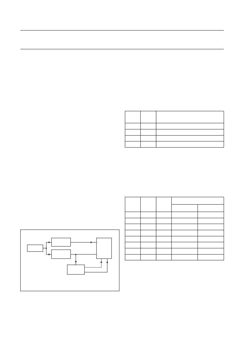
Fig.14 Timing configuration.
handbook, halfpage
VIDEO
DECODING
TUNER/IF
RGB, VDS
FRAME
RGB
MGK464
HSYNC, VSYNC
SYNC
CIRCUITS
SAA5x9x
CRT
DISPLAY
9.22
Display position
The position of the display relative to the HSync and
VSync inputs can be varied over a limited range to allow
for optimum TV set-up.
The horizontal position is controlled by the X0 and X1 bits
in TXT16. Table 23 gives the time from the active edge of
the HSync to the start of the display area for each setting
of X0 and X1.
Table 23
Display horizontal position
The line on which the display area starts depends on
whether the display is 625-line or 525-line and on the
setting of the Y0 to Y2 bits in TXT16. Table 24 gives the
first display line for each setting of Y0 to Y2, for both
625 and 525-line display.
On the other field, the display starts on the equivalent line.
Table 24
Display vertical position
X1
X0
Hsync TO DISPLAY
(μ
s)
17.2
16.2
15.2
14.2
0
0
1
1
0
1
0
1
Y2
Y1
Y0
FIRST LINE FOR DISPLAY
625-LINE
525-LINE
0
0
0
0
1
1
1
1
0
0
1
1
0
0
1
1
0
1
0
1
0
1
0
1
42
44
46
48
34
36
38
40
28
30
32
34
20
22
24
26
相關(guān)PDF資料 |
PDF描述 |
|---|---|
| SAA5X9X | Economy teletext and TV microcontrollers |
| SAA5291APS | IC SW OFF-LINE PS 10/15W 8SMD |
| SAA5297A | Economy teletext and TV microcontrollers |
| SAA5297AH | Economy teletext and TV microcontrollers |
| SAA5297APS | Economy teletext and TV microcontrollers |
相關(guān)代理商/技術(shù)參數(shù) |
參數(shù)描述 |
|---|---|
| SAA5500PS | 制造商:PHILIPS 制造商全稱:NXP Semiconductors 功能描述:Standard TV Microcontrollers with On-Screen Display(OSD) |
| SAA5501PS | 制造商:PHILIPS 制造商全稱:NXP Semiconductors 功能描述:Standard TV Microcontrollers with On-Screen Display(OSD) |
| SAA5502PS | 制造商:PHILIPS 制造商全稱:NXP Semiconductors 功能描述:Standard TV Microcontrollers with On-Screen Display(OSD) |
| SAA5503PS | 制造商:PHILIPS 制造商全稱:NXP Semiconductors 功能描述:Standard TV Microcontrollers with On-Screen Display(OSD) |
| SAA5520 | 制造商:PHILIPS 制造商全稱:NXP Semiconductors 功能描述:Standard TV Microcontrollers with On-Screen Display(OSD) |
發(fā)布緊急采購(gòu),3分鐘左右您將得到回復(fù)。